palikari
Junior Member level 2
I've tried to take whatever suggestions I've found on the net, but I'm still having this problem. I get these errors when I'm trying to simulate.
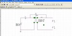
Node N00256 is floating
Node VOUT1 is floating
Node N00214 is floating
Node GND is floating
Node N00227 is floating
Node N00195 is floating
The circuit is attached. What am I doing wrong?
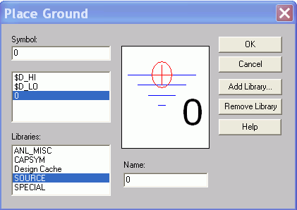
And yes, I had a ground below R2 IN ADDITION to the primary side ground, and I was getting the same errors as well.
Anybody help? Thanks.
Node N00256 is floating
Node VOUT1 is floating
Node N00214 is floating
Node GND is floating
Node N00227 is floating
Node N00195 is floating
The circuit is attached. What am I doing wrong?
And yes, I had a ground below R2 IN ADDITION to the primary side ground, and I was getting the same errors as well.
Anybody help? Thanks.