Continue to Site

Welcome to EDAboard.com

Welcome to our site! EDAboard.com is an international Electronics Discussion Forum focused on EDA software, circuits, schematics, books, theory, papers, asic, pld, 8051, DSP, Network, RF, Analog Design, PCB, Service Manuals... and a whole lot more! To participate you need to register. Registration is free. Click here to register now.

final year project( auto mute for car audio deck)

Status
Not open for further replies.

anatomie

Newbie level 4
Joined
Sep 2, 2012
Messages
7
Helped
0
Reputation
0
Reaction score
0
Trophy points
1,281
Activity points
1,338
Please help me..
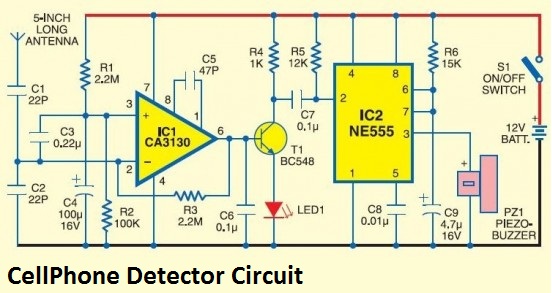
im doing my final year project and i found this circuit in internet...
i was hoping to combine the circuit with other circuit but i just dont know how to simulate the circuit...
i want to simulate the circuit first before combining the circuit..the circuit will detect cell phone signal....
will you help me how to simulate the circuit???
im using proteus software..
im new in this forum...
and i dont know how to preview the circuit that i have connected in proteus...
please guide me...
TQ...


You can preview (simulate the circuit) after component placement and connection. There is a play button on the bottom left of the proteus. Make the circuit and play.
 
Sorry but it is not a good circuit if you want to detect radio energy emitted from cell phones.
For cellphone detection you need something that is able to handle 800 MHz and above.
CA3130 is a low frequency circuit.
Next problem is that even if you replace CA3130 with something better suited, will it still not work as antenna is shortcut to ground over C1,C3,C4.
Replace C3 with a good diode and you is a bit closer a working wide band RF detector.
 

thnks but i already done the connection of the circuit but i dont know how to supply a frequency that is same as cell phone signal so that i can know whether the circuit is functioning or not...


what do you mean that i have to replace the c3 with a good diode??
if i replace it, will it be effect by other component..??
thnks...
 

Analyzing of RF signal path in this schematic is very easy, and no, I can neither find out how to make this circuit functional.
There is nothing in this circuit that can detect RF energy, and if it was, incoming signal is anyway shortcut to ground.
For testing, wind the antenna around a cellphone and call that phone to verify that this circuit is real deaf.
 

thnks...
so did you mean that by replacing the c3 with a good diode will solve this circuit??
 

thnks for your help...
i'll try...

- - - Updated - - -

thnks for your help...
i'll try...
 

there is a buzzer in the circuit that i have shown above...let say if i want to remove the buzzer, should i have to grounded the pin no 3 of the ic or should i just leave it open??
 

Grounding pin 3 is a bad idea. It is the output of the 555. I'm surprised a final year student does not know that and does not know how to find that information. You could just Google "555" or look in the datasheet.
 

dear godfreyl.

come in my class and ask what is 555. :shock:
 

come in my class and ask what is 555. :shock:
Well, that's a little sad, but maybe the 555's not popular, or used much anymore.

However- I think one of the most valuable skills we can learn is how to find information that we need. There's not always someone there to teach us what we need to know.

When faced with an unknown IC or other component, I find the best thing to do is to Google the part number, e.g. "NE555". It's normally easy to find a datasheet, and from that we can learn about the part, what it does and how it works.

It doesn't really bother me that Anatomie doesn't know what a 555 is or does, but I find it strange that he doesn't seem interested to find out, given that he wants to use one in his final project.

Perhaps he can get his project to work by trial-and-error, gluing together pieces of circuit that he doesn't understand until he finds a combination that works, but that doesn't seem like a good way to do engineering.

He asked only if pin 3 should be grounded or left disconnected. How can the circuit do anything useful if there is nothing connected to the output? How can Anatomie use the circuit for any useful purpose if he doesn't know where the output is?
 

The embarassing thing is that circuit which supposedly works is lifted from a group of IIT students project, which is supposed to be a
reputable institution, and those students in turn lifted it from a several-years old web page on an awful website.

Many people blame their teachers and lecturers, the days of respect for elders has gone. Yet I suspect that if
people blame a college/university, a sane person will (usually rightly) just assume that actually it's the students who are not trying to
make an effort to learn. How hard is it to google for 555 if one can google for "cellphone detector" ; )
 

I find it strange that he doesn't seem interested to find out, given that he wants to use one in his final project.
I agree with you guys. This is one of the main problem. Student like us want to get things like a piece of cake.

I am also Final year student of Electronic Engineering and find sometimes in the same situation. but students are not to blame only. I sincerely tell you, whenever i get some circuit problem, I consult internet, books, manuals, senior students (who actually make some circuits) but NOT the teachers. It is very sad and unfortunate because what I ask them, they don't really know, because they don't make circuits by their hands, they get degrees and become teacher.

while edaboard has been really good teacher for me since I joined. I have 3year associate engineering degree now pursuing 4 year bachelor degree. I would probably start teaching career afterwards. I hope to introduce new teaching mechanism so student get interest rather than blaming teachers. All students must remember flowing against the river is hard, if no one helps then you can do it by yourself.
 

its true but i ask you guys that question because a friend of mine told me that information...
so i ask to confirm the information....
however i have look the datasheet and i connect the pin3 with the second circuit...
the problem is that my relay doesn't work properly... can someone told me where i do wrong??
maybe i connect relay pin wrongly...

- - - Updated - - -

this is the circuit that i have combine with the above circuit...

i have connect the n/o pin with 1k resistor series with led...
i also do the same thing for n/c pin so that i can observe the output..
while the com pin with the supply...
like i said earlier, only the relay wont function...
 

hi...i want u ask something...my project almost done thanks to your comment. but i have one problem which my LED is blinking...is there any way to make the LED to stop blinking and always ON..tq

- - - Updated - - -

im sorry again for asking question without checking it before....but now i already understand the situation...if u guys could at least help me with this one...i would really grateful for your help...and again sorry
 

It is very essential and important for home as well as offices.
 

hi...i want u ask something...my project almost done thanks to your comment. but i have one problem which my LED is blinking...is there any way to make the LED to stop blinking and always ON..tq

- - - Updated - - -

im sorry again for asking question without checking it before....but now i already understand the situation...if u guys could at least help me with this one...i would really grateful for your help...and again sorry


Anatomie,i know its of no use answering now, but u can't stop the LED blinking, the theory behind is:
when the antenna catches the radio frequency it is acting just like an AC source; which changes its polarity in every cycle of the AC, so the LED glows when u get positive cycle and stop glowing when the cycle is -ive

if u read this, plz answer, y are u using relay with ur cct. what is the purpose of the relay?
 

CA3130 based mobile detector circuit is working.
 

Status
Not open for further replies.

Part and Inventory Search

Welcome to EDABoard.com

Sponsor

Back
Top