scottlc
Newbie level 4
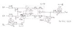
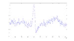
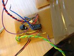
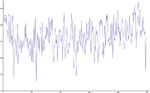
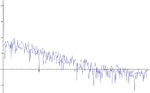
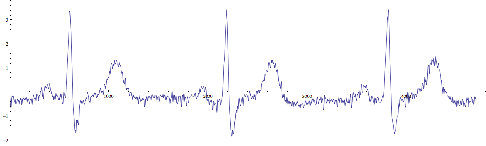
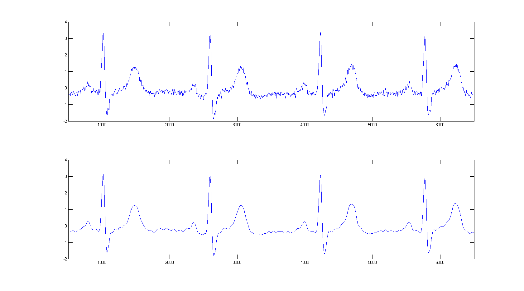
I have built an ECG amplifier circuit using an INA128 instrumentation amplifier with a driven right leg. The circuit is powered by two PP9 batteries for +/- 9V operation and is assembled on strip-board. This circuit suffers from a large amount of broadband noise which swamps the fine detail of the P and T waves. A full circuit diagram, photo and sample data is attached. The data is sampled at 1600 Sa/s and is in volts.
Measurements are made using 3M Red Dot 2330 diagnostic electrodes placed on the wrists with the right leg drive attached to the right ankle. I've also tried using LF347 and OP471 quad op-amps, though they produce roughly equivalent noise output. INA128 gain being set to 10, 30 or 50 seems to have no effect on the signal to noise ratio. Noise is minimal with all three probes connected together (constant signal, within ADC quantisation step). Noise is also minimal when the right leg drive is attached to the right leg and two electrodes are placed side-by-side on the left wrist. I've also tried reducing the value of the resistor on the integrator feeding the INA128's reference terminal with no effect. I've also tried swapping the centre tap of the INA128's gain resistor (common mode) to ground to effectively disable the right leg drive, but this has no effect.
Signal is consistent when measured with a Gwinstek 200MHz digital scope, National Instruments USB-6009 14-bit device, and with the 12-bit ADC input of an ATMEGA168 microcontroller. Noise is consistent when measured away from fluorescent lighting and when completely isolated from mains power, and also when powered from a lab power supply instead of battery.
On the positive side there is no 50 Hz mains interference visible above the noise floor.
At this stage I'm completely out of ideas. Any insight or suggestions would be greatly appreciated.