Continue to Site

Welcome to EDAboard.com

Welcome to our site! EDAboard.com is an international Electronics Discussion Forum focused on EDA software, circuits, schematics, books, theory, papers, asic, pld, 8051, DSP, Network, RF, Analog Design, PCB, Service Manuals... and a whole lot more! To participate you need to register. Registration is free. Click here to register now.

Help with Buck-Boost coverter. Input: 300v

Status
Not open for further replies.

moshik3

Member level 2
Joined
Jun 8, 2012
Messages
47
Helped
2
Reputation
4
Reaction score
1
Trophy points
1,288
Activity points
1,788
Hello.

I am trying to charge a big capacitor to 200-600v DC (selectable)
from the mains line voltage 220vAC.

so the rectified mains gives 300v DC, i need a buck-boost converter to charge the output capacitor to 200-600v.

I have successfully built the boost part, and i currently can charge the capacitor to 600v with the rectified mains (300v DC)
using the UC3842 IC.

I am looking for help regarding controller circuits for buck-boost converters.
all i could find is built-in solution that include the mosfet inside and can accept relatively low voltage, or low output current.

I want to be able to set the output current (charge speed) and use my external MOSFET\IGBT.

Thanks for your suggestions !
 

You can still use a UC3842 to control a buck boost, but you'll need more complicated external gate drive circuitry. For a simple buck boost, your switching transistor is going to have to withstand the full difference between Vin and Vout. So for your design that will be at 900V, so you're practically forced to use a 1200V N channel IGBT. And you'll need a gate driver with a fully isolated power supply as well. So it's fairly more complicated that a simple boost converter.

Are you sure you want a buck boost topology? Are you sure you don't need isolation from the mains? Using an isolated topology would open up your options quite a bit, and you wouldn't need very high voltage devices or fully isolated gate drivers. Also even if you don't want isolation you should consider going for other topologies like SEPIC or Cuk, both of which use low side switching, which again reduces complexity of the gate drive.
 

do you talk about a flyback converter ?
possible, but i want to minimize the need for special\unique components in this product.

so i'm much more easy with a standard inductor than with a unique custom wound transformer.

i don't need isolation from mains, and i can have an isolated supply for 12v for the controls.

what do you think of this idea:
having a UC3842 charge a capacitor with 200v MAX from the rectified mains (no inductor, just the IGBT pulsing the 300v into the buffer capacitor until it reaches 200v.
then based on this 200v capacitor i will have a boost converter that can output 200-600v.

what do you think ?
 

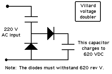
A Villard doubler might do the job. Schematic below.

Since you say the capacitor is large, then you must use diodes that can withstand high surge amps at power-up.

The first capacitor can be a fraction of the value of the output capacitor.

If you wish for the output capacitor to acquire a lesser charge, you might try installing a resistor somewhere. Or, connect a load.

23_1339213536.gif
 
Thanks for the tips -
a capacitor voltage doubler is not possible.
electrolyte capacitors in the doubler are heating and exploding with such a load.
Film capacitors work, but i need about 40uF at least and they start to be expensive.

the high frequency switching is perfect in terms that i can easily limit charge current and that there is no heating parts.

i cant find a practical circuit schematic for a Cuk converter.
all i can find is IC's that do all the work but accept a certain (too low) voltage range.
is there something like the UC3842 for the Cuk converter ? maybe i can use the UC3842 ?

Thanks a lot
 

do you talk about a flyback converter ?
Not really, a flyback still requires high voltage transistors. I was thinking more like a two switch flyback/forward, or something similar.
possible, but i want to minimize the need for special\unique components in this product.
My gut is telling me that this can't be avoided. All reasonable solution involve at least one of the following:
1. Fully isolated gate drivers (for a single stage buckboost)
2. Two inductors (bot Cuk and SEPIC)
3. SMPS transformers (for any flyback/forward/etc converters)
so i'm much more easy with a standard inductor than with a unique custom wound transformer.

i don't need isolation from mains, and i can have an isolated supply for 12v for the controls.
If this is the case then I think a SEPIC/Cuk topology is appropriate. Each has two inductors (they can be coupled, but not really necessary).
what do you think of this idea:
having a UC3842 charge a capacitor with 200v MAX from the rectified mains (no inductor, just the IGBT pulsing the 300v into the buffer capacitor until it reaches 200v.
then based on this 200v capacitor i will have a boost converter that can output 200-600v.
Trying to charge a cap without an inductor won't work, trust me. You wouldn't be able to regulate the capacitor voltage, and something would probably fail quickly. If you use a proper buck converter to step down to <200V, then a boost stage to go to 600V, that could work. But IMO using two independent converter stages with their own controllers is much more complicated than a single SEPIC/Cuk stage.

- - - Updated - - -

the high frequency switching is perfect in terms that i can easily limit charge current and that there is no heating parts.

i cant find a practical circuit schematic for a Cuk converter.
all i can find is IC's that do all the work but accept a certain (too low) voltage range.
is there something like the UC3842 for the Cuk converter ? maybe i can use the UC3842 ?

Thanks a lot
The UC3842 can be made to control a Cuk converter. But since the output of a Cuk is negative, you will need an extra inverting amplifier so the feedback voltage polarity is correct. No big deal. But the SEPIC converter has a positive output, and therefore does not have this "problem."

Keep in mind that the UC3842 is just a control IC. It control any converter topology which is single ended (only operates one switch cycle). So it can do pretty much topology except push pull and half/full bridge converters.
 

Thanks mtwieg !
you are clarifying many options for me. i hope you can continue to help me on this matter, because i am a bit new to SMPS, but i see i can even have good results until now !

I have read about SEPIC now and it looks perfect.
now i understand it can be used with relatively standard inductors and no need for a unique transformer.

can you help a bit with the control part ? will the UC3842 also work for a SEPIC ?
in what arrangement ? i couldn't find any schematic for this.

again, all i am seeing is embedded chips that have the switching inside, and should be connected directly to Vin, and they are maximum about 40v.
I can't find any schematic of a SEPIC using an external mosfet\igbt and using a classic PWM chip.

thanks, looking forward to your reply !
 

Take a look at Vicor BCM products. This can runin reverse and gives you 92.5% eff in a single stage.
 

Attachments

  • BCM352_125_300A00.pdf
    1.2 MB · Views: 150

Status
Not open for further replies.

Part and Inventory Search

Welcome to EDABoard.com

Sponsor

Back
Top