Continue to Site

Welcome to EDAboard.com

Welcome to our site! EDAboard.com is an international Electronics Discussion Forum focused on EDA software, circuits, schematics, books, theory, papers, asic, pld, 8051, DSP, Network, RF, Analog Design, PCB, Service Manuals... and a whole lot more! To participate you need to register. Registration is free. Click here to register now.

250A Mosfet switch over 250A DC Contactor.

Status
Not open for further replies.
Joined
Apr 2, 2021
Messages
4
Helped
0
Reputation
0
Reaction score
0
Trophy points
1
Activity points
34
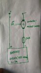
I was thinking of building a Mosfet switching circuit for my 20kWh battery system. DC contactors available in the market are way expensive and those will consume more energy. After a few searches, I found that a Mosfet switch would be the alternative solution for DC contactors. Do you see any issues using the Mosfet switch for higher current applications instead of DC contactors?
 

Hi,

We need more informations.
250A is not 250A. For some calculations we need peak values with timing, or RMS, or average.
The kWh value is not of interest.
The voltage is essential.
We need a drawing / schematic where the switch is located.

Is it for an H-bridge, general (soft start) power OFF/ON, Battery switching (hot swap).

Klaus
 

Hi Klaus,

My system can deliver up to 200A while discharging. And system voltage is 48V. The output of my system will be connected to the inverter.

-Ravi
 

Attachments

  • IMG_20210402_155047.jpg
    IMG_20210402_155047.jpg
    1.3 MB · Views: 106

Hi,

We now can see the battery side ... the other side is open...I doubt this is the real case.

We don't know whether there is capacitive load, inductive load, what current ripple....and whether the charging current goes the same path...

We even don't know why you need a switch at this place at all...
Who controls the switch? And why?
Why not disconnecting the cable, using a mechanical battery switch, or just pull the fuse..

With piece by piece informations .... you need to wait a long time before you get a good answer.

Generally it's not as simple that we can say "do this ... and it will work".
The devil lies in the details.

Klaus
 

Hi,

There will be BMS(Battery Management System) attached to the Battery. During some fault events, BMS will break the connection between load and battery that's why we are using DC contactor. Load here is capacitive where I employ a precharge circuit to protect from the current rush. The Precharge circuit will be in parallel to the Contactor/Mosfet switch.

-Ravi
 

Hi,

I can´t see where the BMS is in your drawing.
I don´t understand... if there is an BMS that will break the connection, why the MOSFET?
I can´t see the precharge circuit in your drawing. It surely needs to interact with the MOSFET (driver) to work properly.

With the given informations I see me unable to give useful feedback.
And I don´t want to annoy you with repeated asking the same questions again and again.

Klaus
 

Mr. Klaus,

First of all, this is a general question. You don't need an entire architecture or line diagram of the system to tell why we should not go for Mosfet Switch. If you consider this is an ESS(Energy Storage System) its obvious li-ion battery will have BMS and if the load is capacitive it will have a pre-charge unit. What you need to understand is in High current ESS, BMS will have an external switch (DC Contactor) not MOSFET on board. How to operate DC contactor and Pre-charge is taken care of by the BMS. If you got a better idea about ESS, Can I develop a high current MOSFET switch instead of using an expensive DC contactor.

Ravi
 

Safety requirements might dwart your idea. What are the specifications for maximal disconnect current?
 

Hi,

A general question results in a general answer.
(I'd like to give more detailed answer ... but it's not possible with this lack of information)

A MOSFET - not to get killed - needs to widthstand:
* the applied voltage. --> thus be sure that there never - niot even for nanoseconds - is a higher voltagevat the MOSFET than specified in the datasheet.
(Especially consider ESD voltage, voltage peaks when inductive loads (even stray inductivity caused by wiring) are switched OFF)
* applied current. --> be sure the current never leaves the SOA given in the datasheet. (Espevially consider overload situations, and when caoacitive load is switched ON)
* overtemperature of it's die --> be sure (ambient_temperature + self_heating_caused_by_ power_dissipation) never exceeds the maximum die temperature given in the datasheet. Not even for milliseconds.

******
Besides this it's not clear what curcuit requirement there are:
* safety: maybe switching with MOSFETS can not fulfill safety requirements, thus is not allowed
* current direction: since a MOSFET is not symmetrical in current flow behaviour. Maybe one MOSFET is sufficent, maybe two, maybe you need additional circuitry. Who knows..
* reliable operation: To safely keep a MOSFET within datasheet specified limits ... one maybe needs some intelligent control (including current and voltage measurement). Who knows? Else any fail in timing or control scheme may lead to explosion and fire.

I'll leave this thread here.
Hopefully others can give you more assistance than I can.
I honesty whish you good luck with your project.

Klaus
 

Having used DC contactors and solid state switches extensively in industrial environments, I can tell you that the reason that DC contactors are so expensive, is that those must be capable of interrupting fault currents.

Unlike AC, with DC one doesn’t have the benefit of a zero crossing every half cycle where the current extinguishes on its own.

I’ll skip the details of a mechanical contactor and go directly to the issues with a solid state one: how to clamp the energy caused by the I-squared fault current times the wiring’s inductance.
Do you have an idea of the current fault level? If your system can provide 250 amps steady state, very likely the fault current will be in excess of 1000 amps.

Then there is SOA. During a fault, the device will go from a low voltage, ultra high current mode to breakdown-level voltage in fractions of milliseconds. What happens between those two states may cause the
semiconductor to fail.

Don’t get me wrong, it can be done. But you must first have a good grip on the required surge energy dissipation.
 
MOSFET switch...yes it can be done...just have enough MOSFETs in parallel to be able to handle the highest surge current that will be seen.
Make yourself a high side drive supply and say a digital isolator to send the activator signal to the fets.....Make sure you have enough snubbering to be able to quench any inductive spike voltages....eg the break in inductive current that occurs when you switch off the 250A in the stray inductance.

The mosfets will need heatsinking

Also have a free wheel diode (or many in parallel) to be able to handle the stray inductive current when the fets suddenly switch off
 

significant protection across a mosfet breaker is required, to limit Vbreaking, this is affected by the peak current to be broken, how slowly or quickly the mosfet is driven off, and the total inductance of the circuit. a full open ckt requires pairs of mosfets source to source, to get the ON dissipation low enough, you need a lot of mosfets in parallel, they do not always share so well during a 2kA turn off event so well matched devices and good layout are critical ... as is a good circuit to gauge over-current and trigger a turn off. good luck ...
 

Status
Not open for further replies.

Similar threads

Part and Inventory Search

Welcome to EDABoard.com

Sponsor

Back
Top