Welcome to our site! EDAboard.com is an international Electronics Discussion Forum focused on EDA software, circuits, schematics, books, theory, papers, asic, pld, 8051, DSP, Network, RF, Analog Design, PCB, Service Manuals... and a whole lot more! To participate you need to register. Registration is free. Click here to register now.
Two points:
- What makes you think the circuit should oscillate? It doesn't implement a standard oscillator prototype?
- Provided, it's a known working oscillator circuit. You need to apply a simulation trick to see the oscillations. Skipping initial transient solution is the easiest one.
There was a recent thread asking the same question but that was about a series LC loop. It has a number of pointers about what a circuit needs in order to oscillate.
In contrast to the linked "series LC" thread, there's no actual closed loop involved with the present circuit. There's a parallel resonant circuit, it can oscillate , if the connected active circuit exposes a negative impedance stronger than the real impedance part of the LC circuit. At least for an ideal transistor (without considering e.g. parasitic package inductances), this will hardly happen.
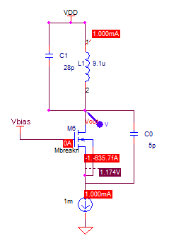
Your circuit is similar to a popular oscillator circuit, but there are a few problems:
The gate and drain of the MOSFET must not be connected together. The gate should be connected to a fixed voltage, e.g. half of VDD.
The small capacitor (C0) should be connected between the drain and source to give feedback.
It may not be able to drive a 50 ohm load. Better to start without a load. After you get the circuit to oscillate, you can experiment to see what load it can drive.
Try change it like in the picture below. I think Vbias should be set to about 1V.
This site uses cookies to help personalise content, tailor your experience and to keep you logged in if you register.
By continuing to use this site, you are consenting to our use of cookies.