Continue to Site

Welcome to EDAboard.com

Welcome to our site! EDAboard.com is an international Electronics Discussion Forum focused on EDA software, circuits, schematics, books, theory, papers, asic, pld, 8051, DSP, Network, RF, Analog Design, PCB, Service Manuals... and a whole lot more! To participate you need to register. Registration is free. Click here to register now.

coin slot connection problem

Status
Not open for further replies.

adrian_miranda13

Newbie level 4
Joined
Jan 18, 2012
Messages
6
Helped
0
Reputation
0
Reaction score
0
Trophy points
1,281
Activity points
1,329
regarding with coin slots, mw too im having a problem in connecting it to the PIC16F877a for the fact that i bought it cheap.
but upon testing individually. im having a reading of 3.5 v (which is considered logic 1 by the microcontroller ) across the coin signal and the ground. yet when im testing it to a 7 segment display to see the on and off state of the coin slot through the LED's, i cant come up with that output.
 

I'm not sure what you mean, do you connect a led directly in the output of the coin device?
If so then it probably can't provide the needed current to turn on the led.

---------- Post added at 10:55 ---------- Previous post was at 10:52 ----------

You should consider using a transistor to level shift the input to 5v,
 

i set my coin slot into normally open state.so whenever i will drop a coin it should change its voltage from logic 0 to logic 1 right?but whenever i am measuring its voltage directly from the coin signal and to the ground,i only get a consistent 3V reading,it seems like it is not switching.,yielding to a non on and off state of the coin slot and counter for every coin dropped will not reflect to the PIC.then i connect a transistor to the coin signal going to the PIC.yet when i tried it to a simple program,and im not able to light the LED.
 

Have you used any load while measuring the output of the coin device?
Maybe it can just provide a very low current.
maybe it is an open collector output, I really don't know.
Is there any datasheet available?
 

thats my problem.the one i bought doesnt have its datasheet for the that i bought it cheap.but upon studying its structure,its just the same with a typical coin selector.yet when i testing it,it doesnt give me a result that will satisfy my testing.but thanks for the consideration for answering my concern.*** bless.
 

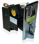
heres the coin slot i bought,take a look at it if you already saw this one, i already fed the coin signal of the coin slot to a transistor with 4.7k ohms resistor and a pull up resistor of 10 k ohms powered by 5 v.yet when im measuring its output,im getting a consistent 3 v.
take a look at the pix.thanks
coin-selector.jpg

and hoping that you could help me what transistor i may used.i already tried using B548C transistor but i didnt have that success
 

I have never used a coin slot so I have no idea of what output to expect.

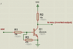
If the output is 3v and you want to level shift to 5v then something like this should work but note that the output will be inverted

NPN_level_shift.gif
 

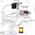
Coin signal is not toggle when every coin is entered, but it' s pulsed, low at a moment and then back to high. Adjust coin signal's speed and finally sensitivity (only if necessary, had done by factory).
coin.jpg
 

Status
Not open for further replies.

Similar threads

Part and Inventory Search

Welcome to EDABoard.com

Sponsor

Back
Top