Continue to Site

Welcome to EDAboard.com

Welcome to our site! EDAboard.com is an international Electronics Discussion Forum focused on EDA software, circuits, schematics, books, theory, papers, asic, pld, 8051, DSP, Network, RF, Analog Design, PCB, Service Manuals... and a whole lot more! To participate you need to register. Registration is free. Click here to register now.

Looking for MOSFET HeatSink

Status
Not open for further replies.

newaisa

Newbie level 4
Joined
Dec 17, 2011
Messages
6
Helped
0
Reputation
0
Reaction score
0
Trophy points
1,281
Activity points
1,347
Hi,

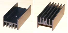
I am looking for a heatsink for my IRF9540 MOSFET. Source to Drain current will go as high as 10A so I think a better heatsink will be required.
Currently the stock heatsink that comes with the mosfet seems a little bit hot, so I need something that is easily installed and small size as there are 16 of these on my PCB.
If anyone has any suggestion let me know. Normally I buy my parts from RS but can't seem to find anything suitable. Please suggest

Thanks

Jason
 

10A at what voltage and how hot does it get? MOSFETs are not always supplied with stock heatsinks so that the term means little to others.
 

it is 5V and up to 10A.

How hot, I am not too sure about actual temperature but I do know it gets hotter than my usual mosfet(don't have any professional equipment to test)
I let it run for hours and it was still OK.

What I meant by stock heatsink is the small metal plate on the back of the mosfet:

**broken link removed**

Now back to the question, is there any heatsink suitable for this component?
 

Check the datasheet for its working temperature. if its match with your temperature. then its ok with the current heat sink. otherwise use a heat sink with bigger surface area
 

otherwise use a heat sink with bigger surface area

Yes that was my intention on my first post. Can you suggest any heatsink? I can't seem to find anything suitable.
Or any guide to finding a correct model would be appreciated.
I know there are many choices out there and that is the problem, I am not sure which is the right one.
 

The metal plate is more usually called a mounting tab. It's meant for mounting the transistor on a separate heatsink but it does act as a small heatsink.

One way of estimating the temperature in the absence of a thermometer is to grasp the tab firmly between thumb and forefinger. If it's not too hot to hold for as long as you want, then it's quite safe. Silicon devices are capable of operating safely at considerably higher temperatures. If you want to mount it on a heatsink anyway, yes, there are many heatsinks types for such transistors (technically, the physical shape and size of the IRF9540 is called a TO-220). One of the types I have in stock is shown in the composite photo below.

19_1324561818.jpg

You can see the threaded hole in the left-hand picture and a threaded groove along the length of the heatsink in the right-hand picture. The first one is for mounting the transistor and the second is for securing the heatsink to a PCB or chassis. Sometimes I also use a couple of square inches of 1.5mm aluminium sheet.

Such heatsinks are suitable for power dissipations up to a very few watts. Higher powers need larger heatsinks.

---------- Post added at 19:54 ---------- Previous post was at 19:29 ----------

I didn't suggest a specific type from a specific source because you haven't given your location.
 
The metal plate is more usually called a mounting tab. It's meant for mounting the transistor on a separate heatsink but it does act as a small heatsink.

One way of estimating the temperature in the absence of a thermometer is to grasp the tab firmly between thumb and forefinger. If it's not too hot to hold for as long as you want, then it's quite safe. Silicon devices are capable of operating safely at considerably higher temperatures. If you want to mount it on a heatsink anyway, yes, there are many heatsinks types for such transistors (technically, the physical shape and size of the IRF9540 is called a TO-220). One of the types I have in stock is shown in the composite photo below.

19_1324561818.jpg

You can see the threaded hole in the left-hand picture and a threaded groove along the length of the heatsink in the right-hand picture. The first one is for mounting the transistor and the second is for securing the heatsink to a PCB or chassis. Sometimes I also use a couple of square inches of 1.5mm aluminium sheet.

Such heatsinks are suitable for power dissipations up to a very few watts. Higher powers need larger heatsinks.

Thanks for showing a good example. Yes something like this is what I am looking for. I tried to "measure" the temperature with my hand...and it is very hot from what i felt. But it didn't burn my hand tho, so just to be safe since these heatsinks are not very expensive in the first place. no harm adding in.

Anyway, yes this seems to be what I need. Do you mind telling me the manufacturer and model? I am not sure whether I can get one or not. It is not easy to find electrical components in this country(Malaysia). I have found several heatsink that I am not sure whether they are suitable or not.

**broken link removed**

The above link is one, but due to the fact the picture is not too clear, part number is written as "AAVID THERMALLOY 5901". Please suggest will it fit?

Or this one:
**broken link removed**

RS is the only website I think that is providing "good enough" service in components purchase. Other than that, not much that I can find.
 

I submitted post #7 shortly before going out for some time. Now that I've had more time to think about your problem, I see that you may need more serious cooling.

I started to type out a long post with detailed calculations and explanations, but decided that it would be better if you supplied some more information about your circuit first.

1) When you said "it is 5V and up to 10A", did you mean that you have 5V between the drain and source and 10A drain current at the same time? Or did you mean that Vdd = 5V and 10A is the maximum current when the transistor is switched into full 'on' condition with the transistor in saturation?

2) Is the 10A current constant or pulsed? If pulsed, what is the frequency and duty cycle?

If you're not sure about the answer to some of these questions, please explain what you want to do with your circuit in as much detail as possible.
 

If you could find the power dissipation by the MOSFET, then u can use the following formula...
T =T (amb)+P (disp.)x[θ(j-c) + θ(disp.)]
Where,
T (amb)= Environmental temperature. ~40°C
P (disp.)=Power dissipated by the MOS
θ(j-c)= Junction to case thermal resistance. for IRF9540: 1.1°C/W
θ(disp.)= Heatsink thermal resistance (Use as lower as 2°C/W)

If the temp comes under 100°C, it is safe...
 

I submitted post #7 shortly before going out for some time. Now that I've had more time to think about your problem, I see that you may need more serious cooling.

I started to type out a long post with detailed calculations and explanations, but decided that it would be better if you supplied some more information about your circuit first.

1) When you said "it is 5V and up to 10A", did you mean that you have 5V between the drain and source and 10A drain current at the same time? Or did you mean that Vdd = 5V and 10A is the maximum current when the transistor is switched into full 'on' condition with the transistor in saturation?

Yes it is drain to source 5V and maximum of 10A to drive my LED. It is just a simple PWM Dimmer for my LED groups. I am using a 15V on the gate with pullup resistor. With that voltage the mosfet should be in fully on/off stage.

2) Is the 10A current constant or pulsed? If pulsed, what is the frequency and duty cycle?

If you're not sure about the answer to some of these questions, please explain what you want to do with your circuit in as much detail as possible.

Yup as mentioned, pulsed. Currently I am using roughly 400Hz (actually more than enough for led refresh rate)
The whole power part of my design is that I am using a TLC5940 as a 12-bit 16 channel PWM led driver to "drive" these pmos. below is a rough sketch. I know the PMOS is reversed in the diagram, but not the actual connection. The LED I bought have built in resistor so didn't bother showing it either. I have let the PMOS to run for 5 hours until now without any problem. But still hot. So a heatsink will ensure smooth operation for long term. I am considering about adding in a small fan and decent heatsink on these PMOS. Right now they are running open air and later on I will put them into a box for on-site usage.

**broken link removed**
 

The heatsink I showed as an example is a no-name product that I bought over the counter, so I'm afraid it's not possible to give you a model number. I've had a look at the heatsinks offered by RS Malaysia, but there's a problem in choosing specific models to suggest because some things in your account don't quite add up correctly.

The specs for the IRF9540 give the on-state drain-source resistance as 0.15Ω. At 10A it should dissipate 10²*0.15W = 15W. Even at a 50% duty cycle, it's still 7.5W. The thermal resistance is given as 80°C/W which means that, even at 50% duty, the transistor temperature should rise by 600°C above ambient if it's left running for an appreciable length of time. Yet you said that it's not hot enough to burn your fingers. The only conclusion I can make is that you're running it at quite a low duty factor.

With these in mind, the only suggestion I can make is to use this **broken link removed** or a similar model. The 9°C/W thermal resistance is a dramatic reduction from the 80°C/W of the bare transistor and should lower the temperture considerably. An alternative is to use one of the wider heatsink models and let several transistors share it, taking care to electrically insulate each transistor from the heatsink with mica or a synthetic thermally conductive material.
 

Maybe i am kicking in an already closed door.
But if You Already have 15 Volt to drive the mosfet why not use a simple voltage doubler and drive a n-mosfet with opto and totempole.
This would drasticly reduce your need for a heatsink and it would improve your switching time of the mosfets (by reducing your switching losses)
Maybe reducing your losses might be a better option then adding the heatsink.

(tomorrow i'll be on the road but i will check in tomorrow night)

hi walkura,

the reason that I am using a PMOS instead of NMOS is due to TLC5940 is an active low PWM device. I was thinking to go with a inverter and a NMOS or just a PMOS. In the end I opt for PMOS.
And I thought few hundred Hz wouldn't hurt that even tho the switching time will be doubled or worse.
Update: The thing ran throughout the night without failing. I hope they're not dying slowly.

---------- Post added at 10:20 ---------- Previous post was at 10:13 ----------

The heatsink I showed as an example is a no-name product that I bought over the counter, so I'm afraid it's not possible to give you a model number. I've had a look at the heatsinks offered by RS Malaysia, but there's a problem in choosing specific models to suggest because some things in your account don't quite add up correctly.

The specs for the IRF9540 give the on-state drain-source resistance as 0.15Ω. At 10A it should dissipate 10²*0.15W = 15W. Even at a 50% duty cycle, it's still 7.5W. The thermal resistance is given as 80°C/W which means that, even at 50% duty, the transistor temperature should rise by 600°C above ambient if it's left running for an appreciable length of time. Yet you said that it's not hot enough to burn your fingers. The only conclusion I can make is that you're running it at quite a low duty factor.

With these in mind, the only suggestion I can make is to use this **broken link removed** or a similar model. The 9°C/W thermal resistance is a dramatic reduction from the 80°C/W of the bare transistor and should lower the temperture considerably. An alternative is to use one of the wider heatsink models and let several transistors share it, taking care to electrically insulate each transistor from the heatsink with mica or a synthetic thermally conductive material.

Where did you see the 80C/W figure? I can't find anything that high in my datasheet. Or am I looking at the wrong place?
http://www.irf.com/product-info/datasheets/data/irf9540n.pdf

I am actually running 50-100% continuously on the fading part. But if your calculation is correct, I really don't know what is going on here. My ambient temperature is around 27C.
I know they are running fine right now. But I really am curious to find out as per what you said about the actual heat might be generated.
 

The thermal resistance is given at the bottom of the first page in your datasheet. My datasheet is by Harris and they give somewhat higher figures than on yours for both rds(on) and thermal resistance, but they are still in the same ballpark range. Going with the figures on your datasheet, the power dissipation should still be 0.117*10²W = 11.7W at 100% duty and about 5.85W at 50%. With a thermal resistance of 62°C/W, that's a temperature rise of 725°C and 363°C respectively!! That's enough to destroy the transistor in minutes if not seconds.

Those figures for rds(on) and thermal resistance are guaranteed maximums, but even if the actual numbers for your sample are somewhat lower, say 0.1Ω and 50°C/W, that's still a temperature rise of some hundreds of °C. This is why it's desireable to select transistors with low rds(on) when high current levels are involved.
 

Status
Not open for further replies.

Similar threads

Part and Inventory Search

Welcome to EDABoard.com

Sponsor

Back
Top