Continue to Site

Welcome to EDAboard.com

Welcome to our site! EDAboard.com is an international Electronics Discussion Forum focused on EDA software, circuits, schematics, books, theory, papers, asic, pld, 8051, DSP, Network, RF, Analog Design, PCB, Service Manuals... and a whole lot more! To participate you need to register. Registration is free. Click here to register now.

230vac transformer Output to pcb.

Status
Not open for further replies.
I'm wondering that as well.

The transistor is a 2SA1757 made by Rohm. It is a high speed switching transistor but there are no parts on your board which suggest it is used in a switching application so I think it is being used as a general purpose PNP transistor in this case. You can't tell anything about the board or the transformer from the part number I'm afraid.

If you want, you can try to test it but without proper analysis equipment all you will get is a go/no-go check:

If you have an analog testmeter (with a moving needle to show the reading)
use the lowest OHMs range, measure by swaping the probes around between the three pins, in one position you should get a reading from one pin to the other two, all other positions should give no reading.

If you have a digital meter (LCD or LED readout)
use the diode test range and do the same thing, you should get a reading of about 0.6 from one pin to the other two and nothing in any other position.

Brian.
 

I dont seem to be understanding this chat thing, i no abit on how to solder and fix broken bits and stuff, but when it comes to the components im lost. i dont have the knowlege you people have, wish i did. i have downloaded a data sheet for the transistor, it says its a silicon power transistor, 60v , AM I ON THE RIGHT TRACK WITH THIS, im trying to learn,,help,,,.thanks..
 

You have the correct data sheet but it will not be of any use to you!
It shows the maximum allowable voltage and current for the transistor and a few other parameters that are needed by a circuit designer to make sure it does what is needed of it. You can't work backwards from a data sheet to see why your charger doesn't work though. From your photographs we can see the circuit is very simple so the fault should be easy to fix. Where you lack knowledge is in recognizing the 'building blocks' that all designs are made up from. It's something you learn from experience and in no way am I criticizing you for lacking knowledge.

I've been doing this for more than 40 years so let me tell you how I see the board:
1. It has four identical 1 Amp diodes sitting side by side. This tells me they are wired as a bridge rectifier for converting the transformers AC output to DC for the battery.
2. C1 is probably a reservoir capacitor and it is small so the power is not particularly 'clean', this doesn't matter if it is just a battery charger.
3. The transistor Q1 is on a heat sink to keep it cool so it is probably wired as a series pass element to regulate the charge current.
4. The big white resistor is almost certainly also in the charge current path. It's that big and they type so it can withstand high temperature.
5. Something makes one or both LEDs indicate the charge level, this needs a voltage sensing circuit and is probably what the four small transistors are there for.

There are other clues, such as the positioning of the white wires labeled 'AC' which almost certainly go to the transformer secondary and the discoloration of the board shows which parts get hot. One resistor is mounted in a hole so it is probably intended to run hot all the time and is therefore almost certainly a bleed resistor to maintain a minimum load on the charger.

Without seeing it in the flesh I can't confirm my guesses but as you can see, quite a lot of diagnostics is based on a 'most likely scenario' which in turn comes from seeing this kind of thing before.

Brian.
 
hi, thank you for the reply, wow i have alot to learn. as you said i dont have the knowlege, would not even no where to start if i was building a pcb. i would just love to be able to sit and learn, i no all the info is in front of me,its just understanding and learning to be able to repair it.
 

hi all, well here is where i am with this problem, a friend of a freind has got the power back to the transformer it has a 20v output now, and told me the pcb was all fine. The thing is now, he has only bypassed the secondary output with a peace of wire, even thou its working i cant use it, i just dont trust it. i would like some help on what type of fuse i need to replace on the secondary output to make it safe for use, thanks...
 

If you mean your friend has shorted out the transformers internal fuse, you didn't do the resistance check properly as suggested several messages back, that would have told you it was at fault.

As for an external fuse, it isn't quite the same thing but it will be better than nothing: Your maximum continuous load is 1A so wire a fuse of 1.5A, preferably an anti-surge type in line with one of the white transformer wires. The extra 0.5A in the rating will ensure it doesn't burn out in normal use but is small enough that a fault will still blow it.

Brian.
 

hi, thanks for the reply. thats what my mate said when he seen what i had done,lol. no to good with the numbers, so i guess i will keep to the basic, much safer for everyone. anyway so the peace of wire he put on will be ok to leave there and just get him to put the 15amp inline fuse on the secondary output is that right? i wasted alot of time with this, takeing things apart that i did not need to, will no next time, call someone else lol.. thanks for the help.
 

hi, sorry missed the point out, just been looking on the net for on of them fuses, is there a type you recommend theres so many to choose from :???: .
 

The most common would be a 20mm size, if you can't find 1.5A a 1.6A will do just as well. You will need a holder for it, never try to solder to the ends of the fuse, remember that fuses work by melting the wire inside them and you will find the soldering iron is hot enough to do just that!

Alternatively, there are wire-ended fuses which you can solder straight to the board but these tend to be more expensive than a standard 20mm fuse and holder combined.

Brian.
 
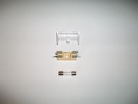
hi, well the new parts have arrived, the problem is now what do i use to connect them as i cannot solder the fuse holder to the secondary output wires. any ideas anyone?..
 

Use the hole in the fuse holder to mount it somewhere inside the plastic case, it doesn't really matter where as long as it doesn't touch anything else.
Unsolder 1 white 'AC' wire from the PCB and re-solder it back to one end of the fuse holder, use the little tag that sticks out from the end.
Using a new length of wire, solder one end to the other tag on the fuse holder and the other end of the wire to the 'AC' connection where the original white wire used to go on the PCB.
Finally, fit the fuse in the holder and fit the clear plastic guard over it.

Done!

Brian.
 
hi, thanks for the reply. I miss understood the soldering bit sorry, you ment dont solder directly to the fuse.. I got it now will give it ago, thanks for the info...
 

hi, well this is how i got on, soldered a brown wire from the transformer secondary, passed the brown wire under the pcb to the fuse spure, then took anothor brown wire from the other end of the spure back to the pcb AC input.. . I then soldered a yellow wire from the transformer secondary straight into the pcb AC input. I need for it to be checked over befor plugin the charger in. many thanks...
 

Looks very good!

Just check the fuse doesn't touch anything else when the small board is refitted - otherwise it's 100% Well done!

Brian.
 

hi, thanks for the reply. I have just switched the charger on with no problems, untill i insert the battery it blows the new fuse after about 5 seconds, any ideas....
 

hi all, right i have replaced the fuse and left the charger running for about 4 hours without any problems. I have done a test on the charger outputs a it reads 20.15Vdc. I also tested the battery and i get a reading of 12.73Vdc. Im trying to get my head around this, could it be when i insert the battery its drawring to much voltage or current from the transformer to the pcb to the battery, so it must be drawring to many amps for the 1.6amp fuse to blow, is that right?. so i think its down to a component on the pcb or the battery, or would it be the transformer itself? im just trying to get my head around this....:?
 

I'm not sure why the fuse died, I based the rating on the numbers on the label in your photograph but perhaps they showed average power and not peak if a discharged battery was attached. If that was the case, you could safely increase the fuse rating to say 2.5A without making it unsafe.

It is normal for the voltage to be higher from the charger than the battery. The reason is that in order to put charge into the battery you have to 'force feed' it a higher voltage than the cells themselves would normally hold. If you think of it the other way around, if the battery had higher voltage than the charger it would discharge into the charger rather than the other way around. I'm guessing the cells inside your battery pack are Nickel Cadmium ones as used in most power tools. These are charged with a constant current, in other words the voltage from the charger is allowed to change so that it is only higher than the battery enough to allow a fixed amount of current flow. As the battery charges up, it's voltage increases and the charger also increases it's voltage so it is always just a bit higher and can therefore keep 'pushing' current out.

It is possible, in fact quite likely, that if your battery is more than a year old or has had a lot of use, one or more of it's internal cells may have gone short circuit. When this happens, the battery loses capacity and the charging current may increase, that could be the cause of your fuse blowing. It isn't easy to confirm this unless you can open the battery casing. Usually it will contain several cells joined in a chain, each cell gives 1.25V (if it is good) so for a 12V battery you probably have 10 cells in the chain. What you do is charge it up for an hour or so, then unplug it from the charger and leave it for a few hours. Then using your testmeter you measure the voltage across each cell in turn, a fully charged one will show a little over 1.25V and ones that are failing will have dropped below 1.25V. Most faulty cells will have dropped to almost zero.

Be very careful if you try to open the battery pack. If you accidentally short out one or more good cells a huge current could flow and cause overheating or even an explosion.

Brian.
 
hi, thanks for the reply. I always wondered why the charger current was higher, so how does the charger no when the battery is full ? anyway i will have ago at taking the battery apart and your safty warnings will be of great use, thank you....

---------- Post added at 22:58 ---------- Previous post was at 21:28 ----------

hi, well took the battery apart and tested them all including the one on top, they all have a reading of between 1.6 and 1.7Vdc and all look ok apart from the glue of the back of the insulating pads which i had to remove. I also had to tape a metal clip that keeps poping off, but all went ok thanks....
 

Status
Not open for further replies.

Similar threads

Part and Inventory Search

Welcome to EDABoard.com

Sponsor

Back
Top