design.s
Newbie level 3

- Joined
- Mar 20, 2012
- Messages
- 3
- Helped
- 0
- Reputation
- 0
- Reaction score
- 0
- Trophy points
- 1,281
- Activity points
- 1,305
Hi,
I've been trying to measure 230 volt AC with PIC18F4550 to trip a AC generator on overvoltage or undervoltage and display the reading on an LCD.
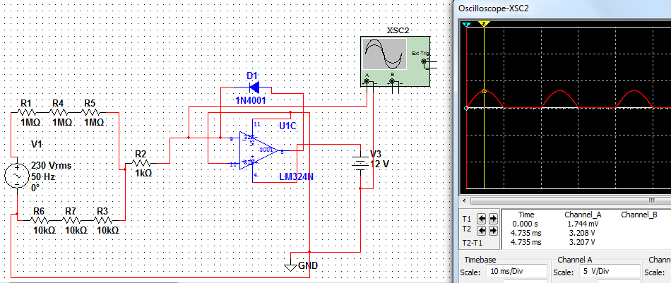
Currently, I'm using a 230~6V (1VA) transformer along with resistor divider and a diode. But since there's a 0.7V drop across the diode, im going with the precision rectifier as in this figure:
I would like to eliminate the transformer since i will be isolating the board completely with a cover, so there isnt any physical contact of the user with the board directly, and in addition i'll be using MOV and PTC fuses . I prefer not using galvanic isolation to reduce the bulk and cost. Would it be appropriate to connect the AC neutral line to the digital ground (Vss) of the microcontroller directly for ground reference for ADC measurements or is there a way to neutral reference by any other means?
thanks
I've been trying to measure 230 volt AC with PIC18F4550 to trip a AC generator on overvoltage or undervoltage and display the reading on an LCD.
Currently, I'm using a 230~6V (1VA) transformer along with resistor divider and a diode. But since there's a 0.7V drop across the diode, im going with the precision rectifier as in this figure:
I would like to eliminate the transformer since i will be isolating the board completely with a cover, so there isnt any physical contact of the user with the board directly, and in addition i'll be using MOV and PTC fuses . I prefer not using galvanic isolation to reduce the bulk and cost. Would it be appropriate to connect the AC neutral line to the digital ground (Vss) of the microcontroller directly for ground reference for ADC measurements or is there a way to neutral reference by any other means?
thanks


