rickyjar
Member level 2
User “Zuraf” made his own CNC milling machine
The concept of the machine was germinating in the user’s mind and on paper. Unfortunately, he ran out of computational power to generate 3D graphics and manage a big number of threads at the same time, therefore he decided to employ the benefits of technology, thus the rest of the project was created in Autodesk Inventor.
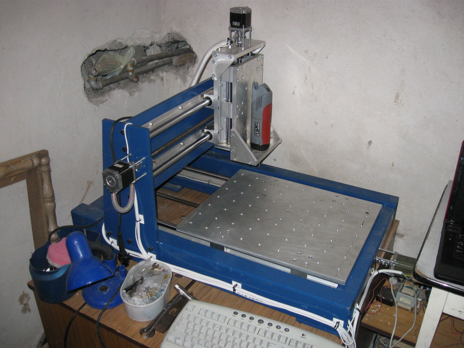
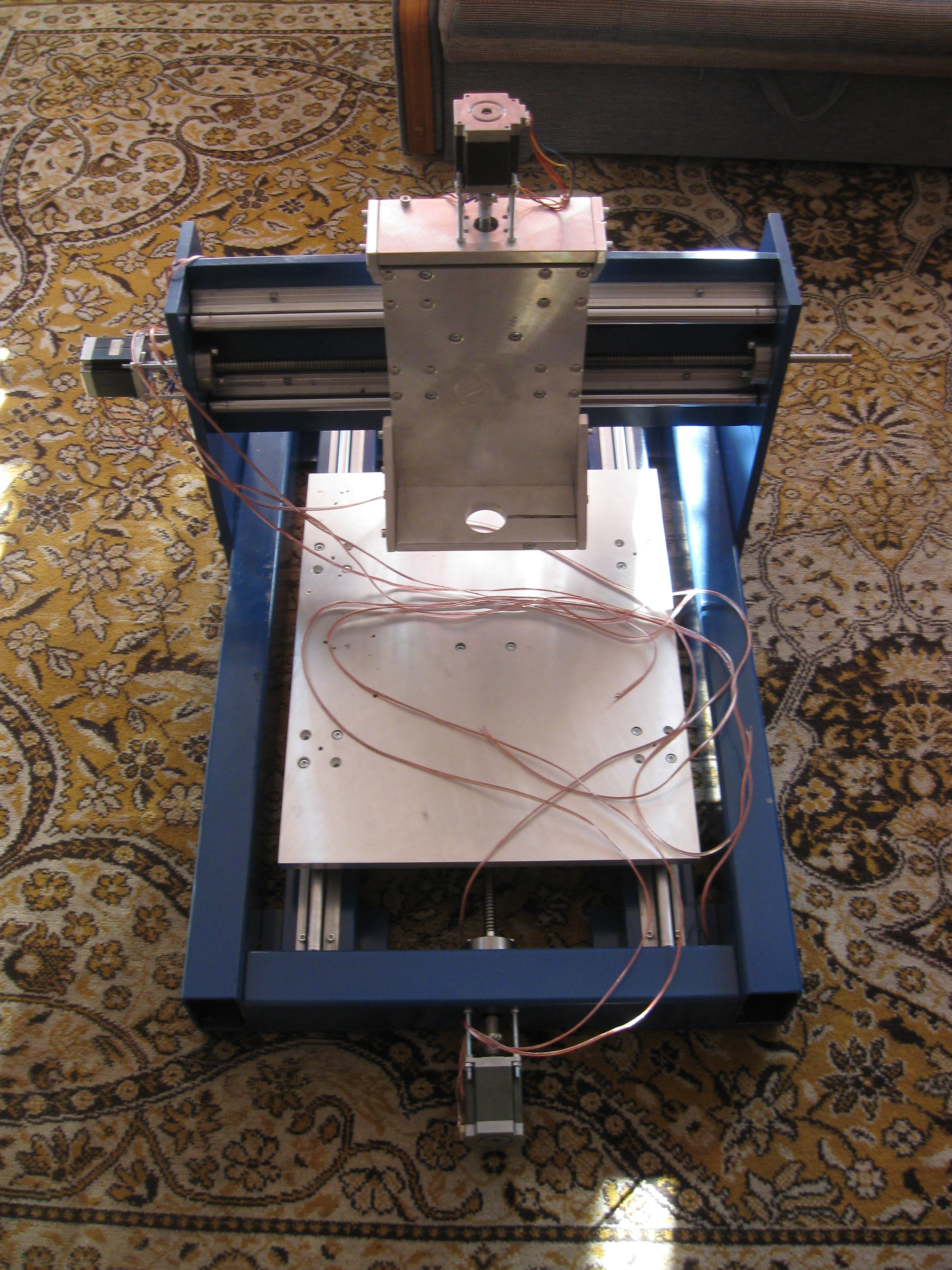
The initial assumptions were not too much excessive. Working area was supposed to be about 300x300x150 and be mainly made of parts taken from old printers, and the budget was supposed to total about PLN 1000. Finally, working area is 540x440x150, and the budget was tripled.
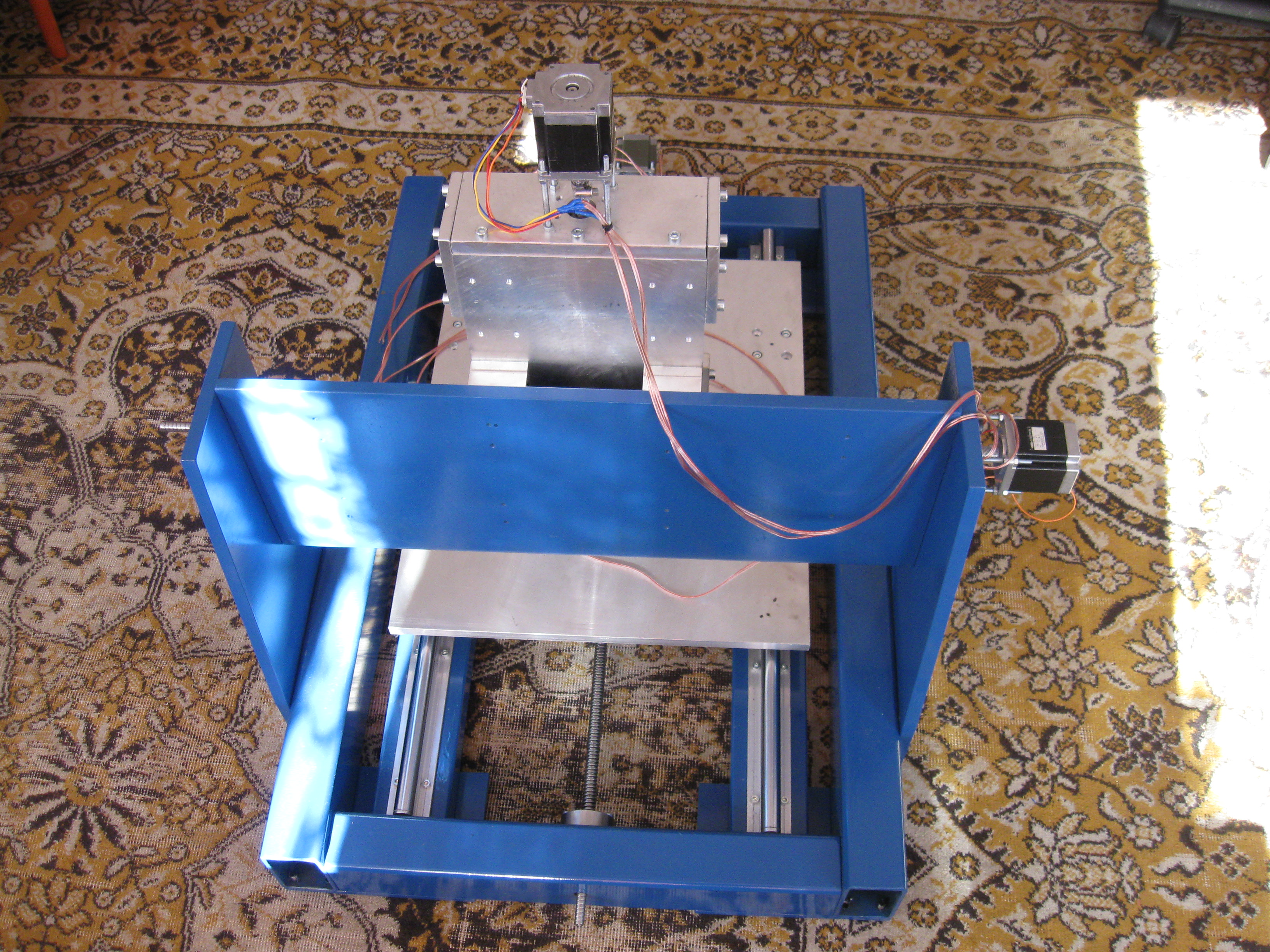
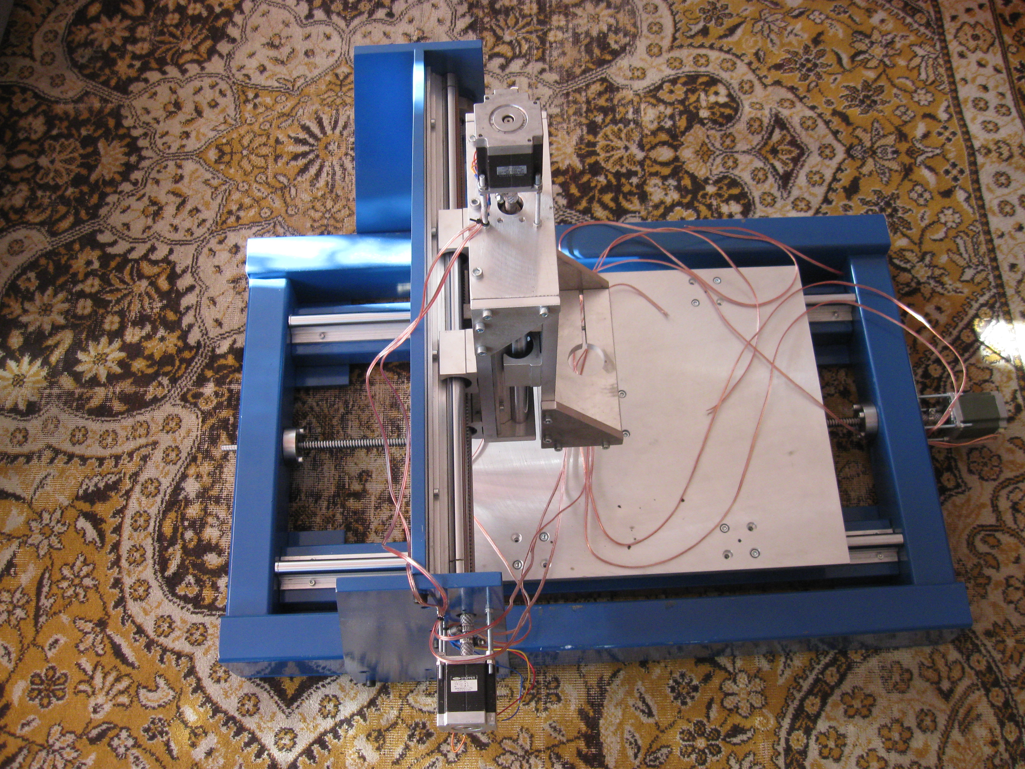
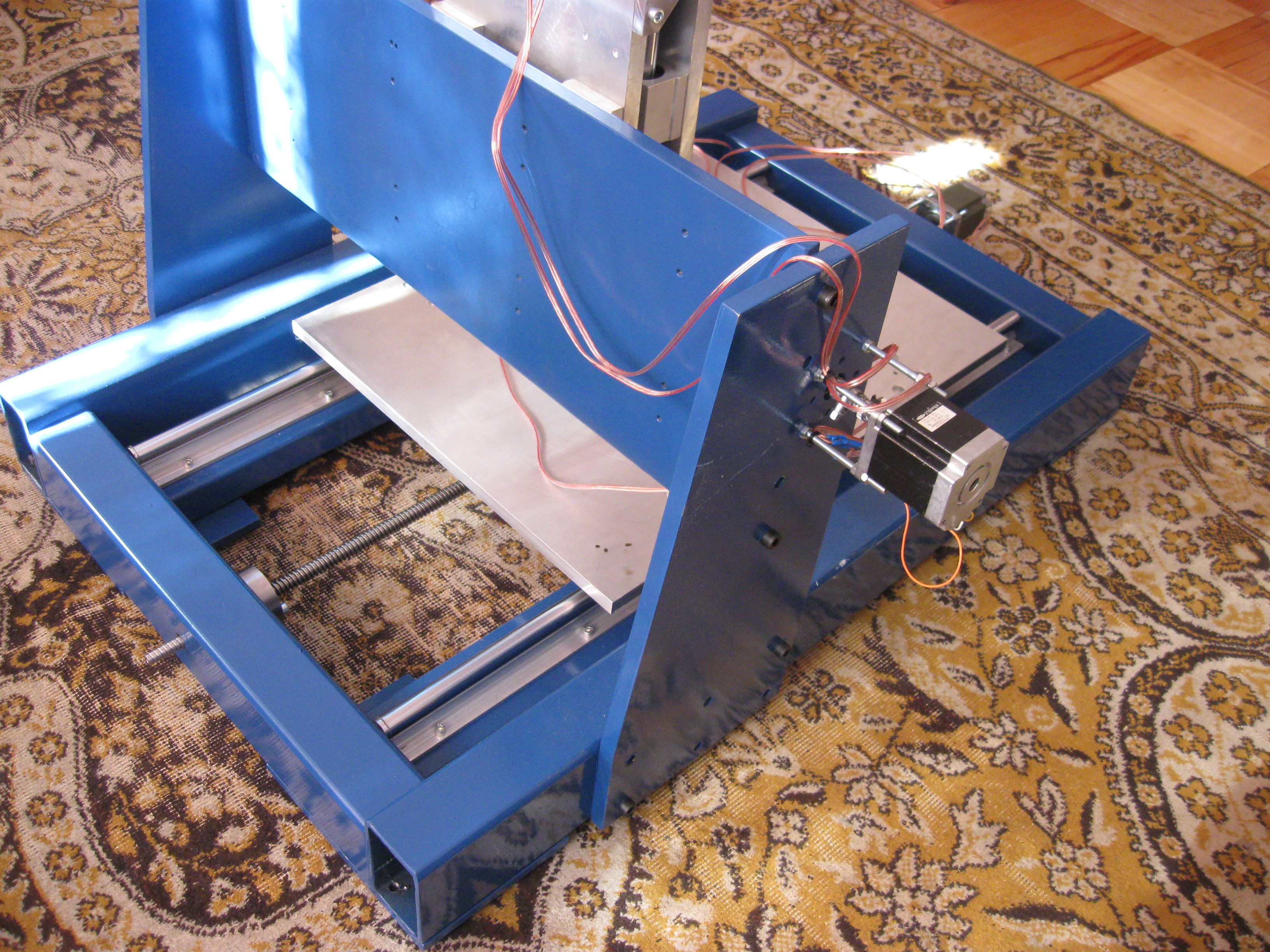
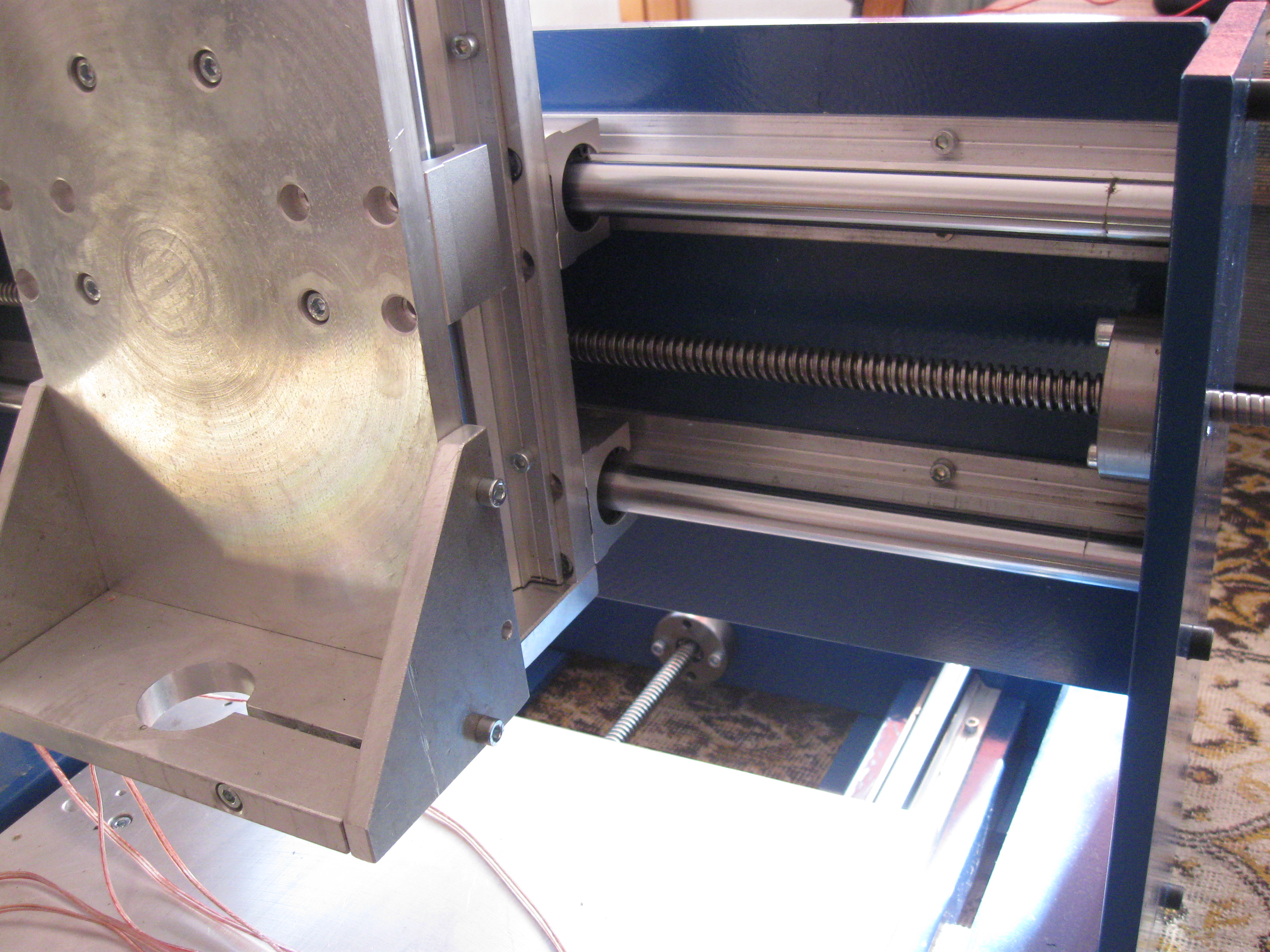
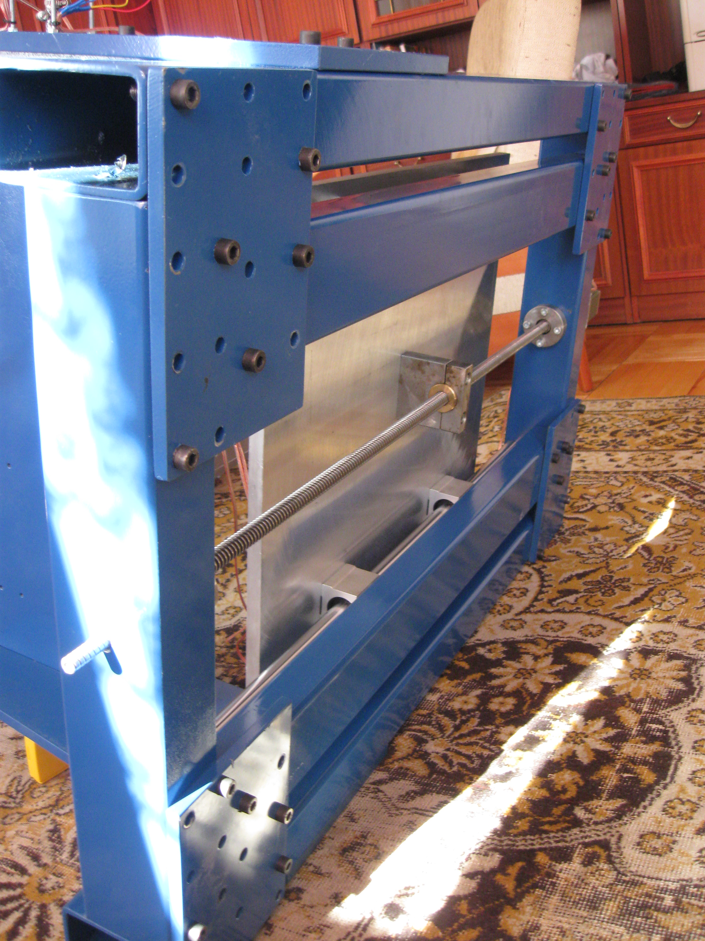
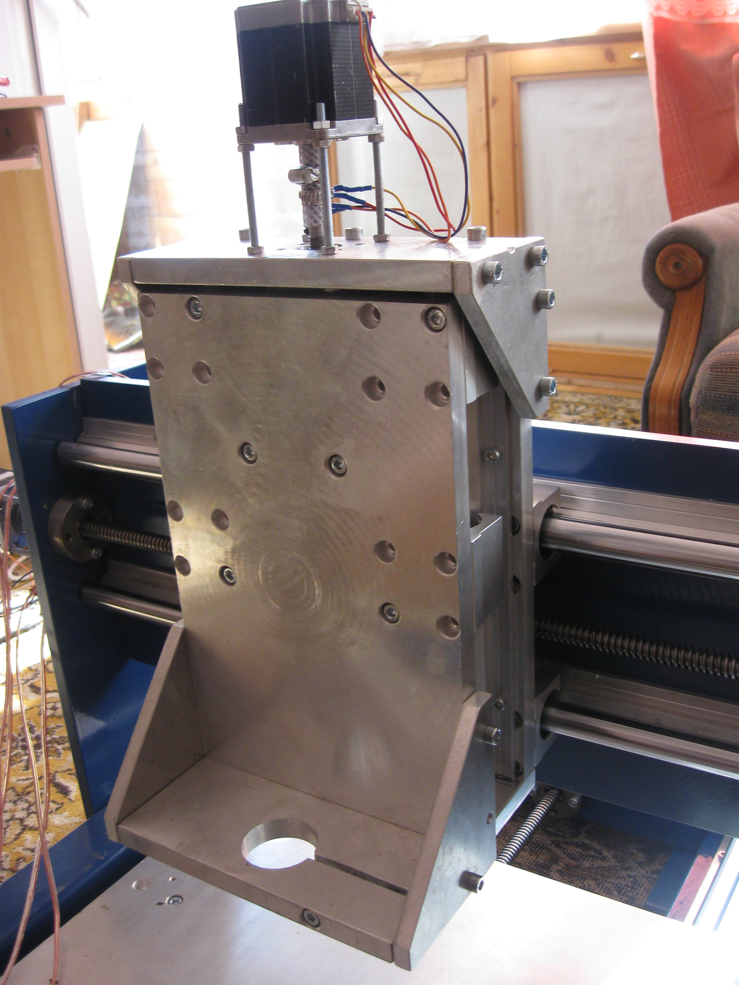
The construction was made of 100x60x5, 80x60x4 and 80x40x4 steel profiles. The gate was cut out of 12 and 15mm steel metal sheets. All the surfaces screwed were machined/ground. The runners, which were used, are rollers supported with fi20. The table and basic elements of the X and axes were made of 15mm aluminum metal sheet.
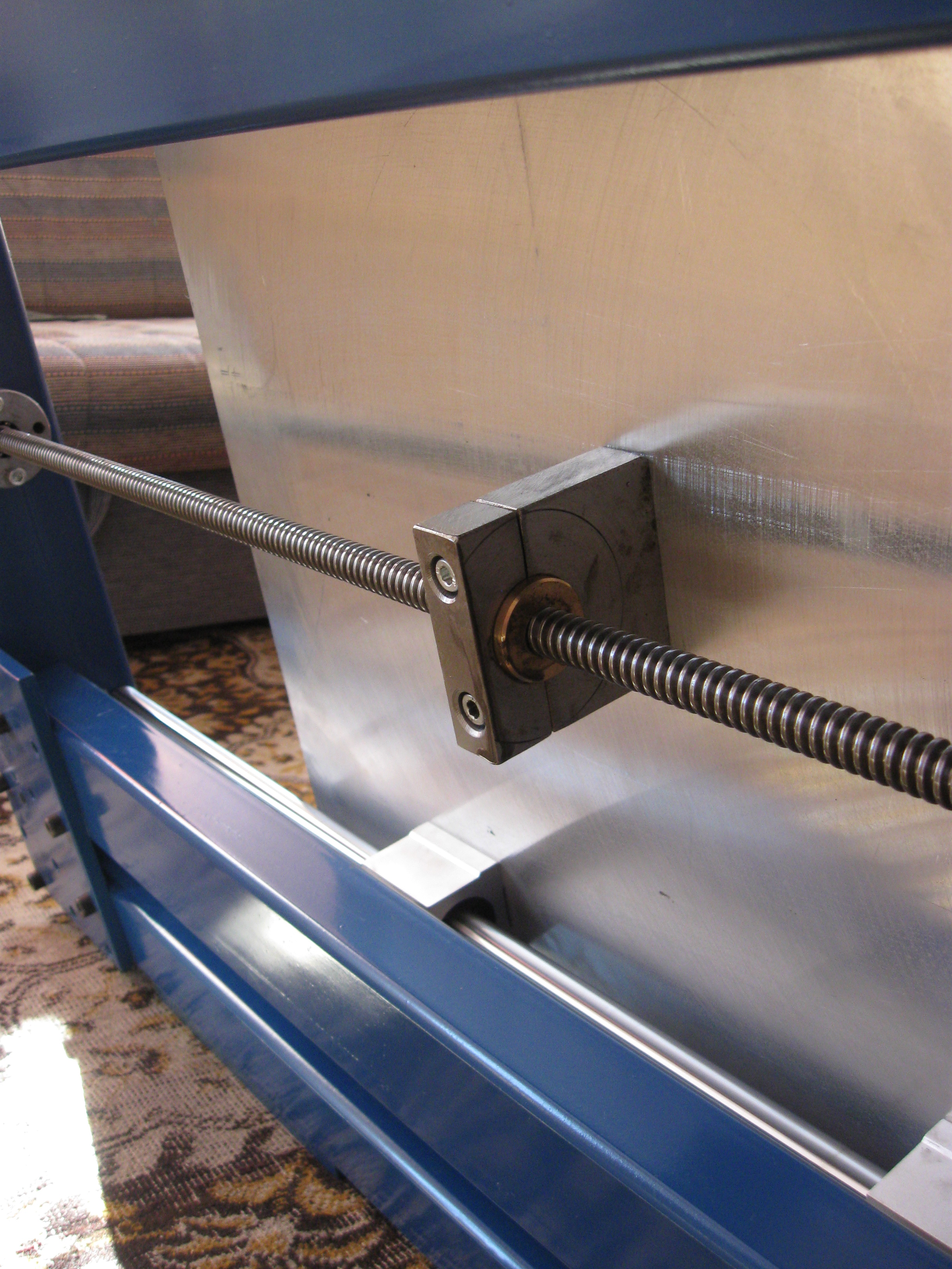
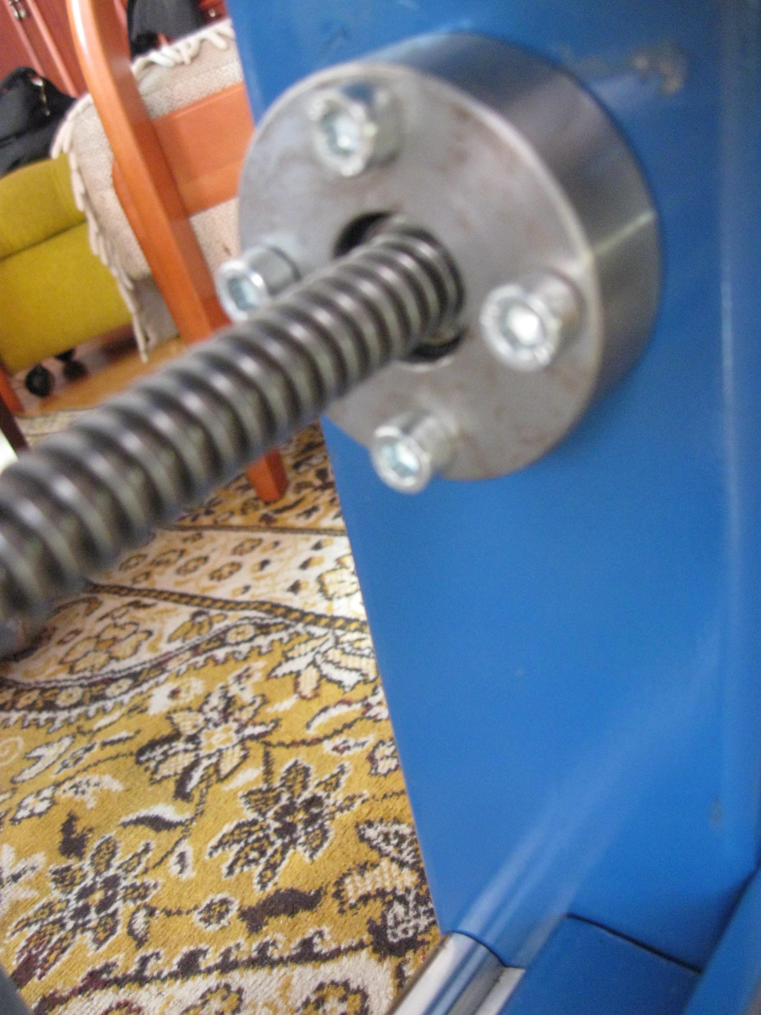
The drive consists of Tr14x4 spindles fixed in two bearings. From the engine’s side, there is a double-row angular contact ball bearing (3200), whereas the other side of the spindle is supported with a self-aligning ball bearing (2200). The spindles were lathed for the bearings and from the engine’s sides they were threaded for the nut supporting the bearing.
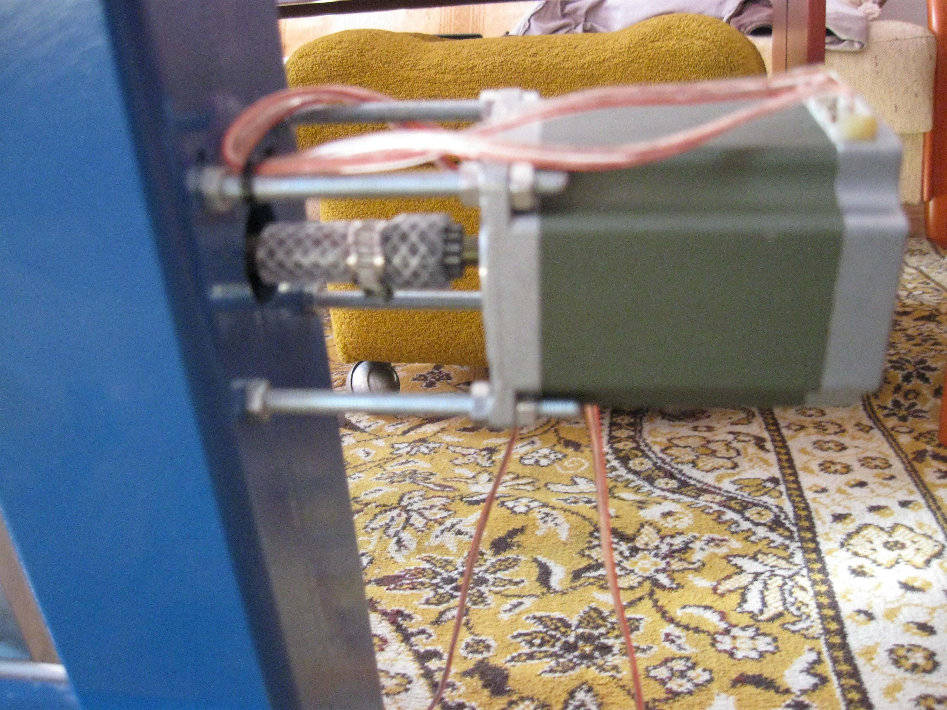
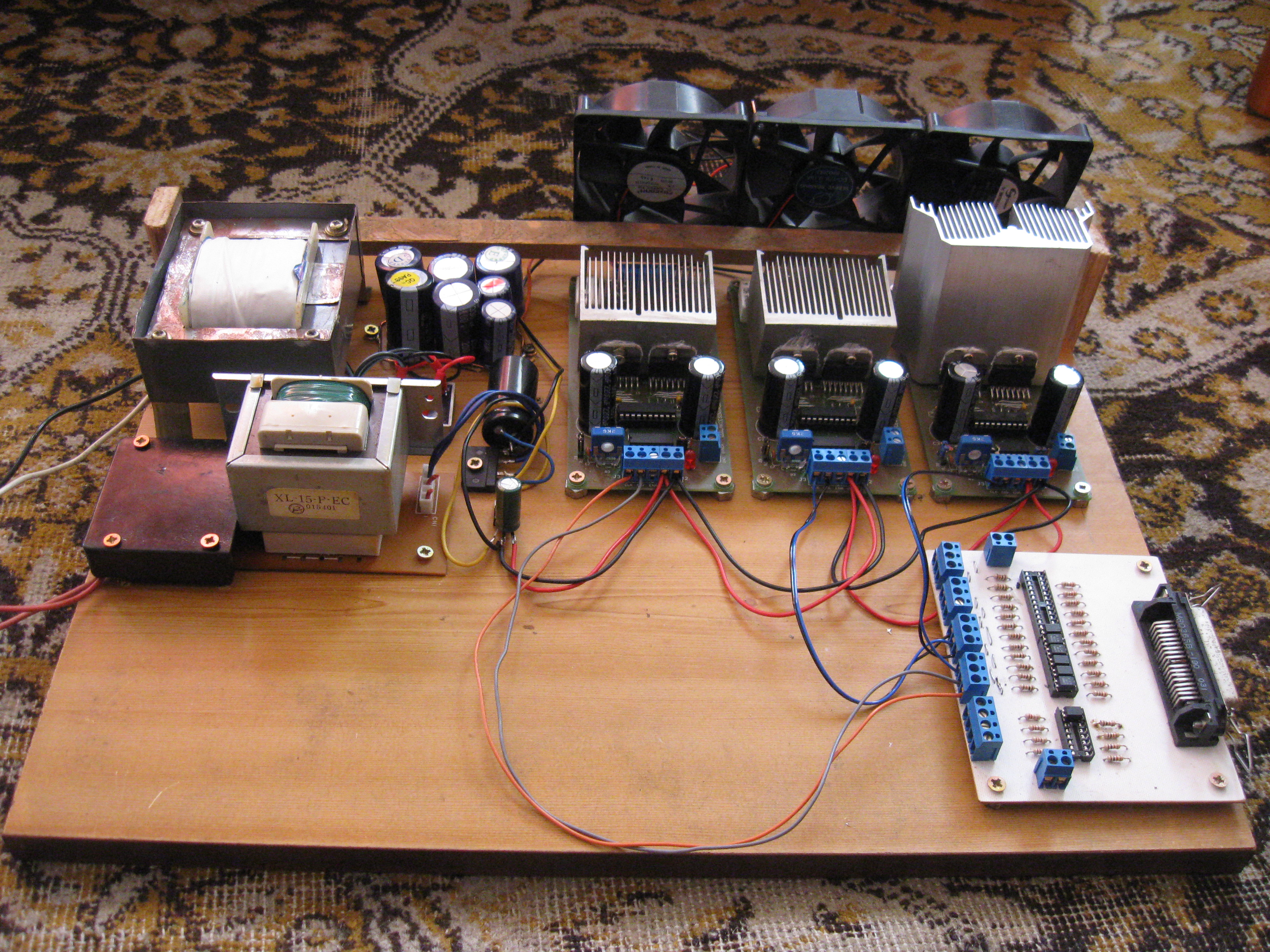
SanyoDenki 1.4Nm and 2xMinebea 1.3Nm engines were used. The engines were coupled with screws by means of an armored hose clamped with four band clips. Electronic appliances were provisionally assembled on a piece of a particle board. The electronic appliances are supposed to be placed inside a steering computer. The SSK-B02 boards were used. Two 24V/680VA transformers were adapted from an old Wilder. After rectifying, they gained 35V voltage. Thanks to the use of that big transformer, voltage during power consumption of about 6-7A, goes down by 1V. It contributed to a significant increase in performance - 4500mm/min in empty working circles instead of 1000mm/min. A Kress 1050 spindle was used.
Gallery:


Link to original thread - Frezarka CNC. Półprofesjonalna metalowa konstrukcja skręcana by Zuraf