Continue to Site

Welcome to EDAboard.com

Welcome to our site! EDAboard.com is an international Electronics Discussion Forum focused on EDA software, circuits, schematics, books, theory, papers, asic, pld, 8051, DSP, Network, RF, Analog Design, PCB, Service Manuals... and a whole lot more! To participate you need to register. Registration is free. Click here to register now.

220VAC Input Burning Problem

Status
Not open for further replies.

apsua

Member level 3
Member level 3
Joined
Feb 13, 2015
Messages
62
Helped
1
Reputation
2
Reaction score
1
Trophy points
8
Activity points
538
Hello,
I have an 220VAC input circuit as below:
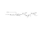
secCircuit.jpg

The reason we are using varistor in the circuit is to prevent the unwanted electromagnetically produced voltages in the shaft around over 100 Volts. This was working well, but recently in some place with high voltage inputs of 230-240VAC started to appear. If the voltage is high continously for some time, the resistor 10k, or varistor burns.

Can you advice a better replacement?

Thanks.
 

Hi,

The varistor is a protection circuit, but here it is not used in this way.

Some varistors can not withstand this current for a long time. As so often: the datasheet will tell you.
The circuit not well designed.

The "140A" are not "140 Amperes", am I right?

Klaus
 

Thanks for reply.
No, 140A is a symbol.
Can you give an idea to what to do to make it better?
 

Hi,

"130V varistor 7mm" is no specification.

You need a partname to find the datasheet.

Additionally the optocoupler LED won't withstand the high reverse voltage.

******
For a good design you need to tell the full circuit function. I mean values, not that much text.

It seems the optocoupler should not trigger below a certain voltage level.
And it must trigger above a certain voltage.
Then there is a low pass filter at the output of the optocoupler and a three stage amplifier. What's it's exact purpose?
timing, currents, voltages..

Klaus
 

Hello,
The varistor partname is 7D201K.
You say the optocoupler LED won't stand the high reverse voltage, should I use two direction dioded optocoupler, like SFH620A-2?
There is three stage amplifier, the 140A voltage at the end is used for operating relay.
The input is the mains voltage, and I don't want the unwanted voltages to trigger the output.
Any other information needed?
 

Problem 1: The LED current is probably too high.
Problem 2: The LED reverse voltage is monstrously too high. Most are less than 5V rating, you give it ~320V peaks.
Problem 3: Varistors drop in resistance as their voltage threshold is exceeded. If you are trying to protect the LED it does the opposite.

I suggest increasing the 10K to something between 68K and 100K and wiring the LED across a bridge rectifier. If you place the bridge on the LED side of the resistor you can use low voltage diodes (IN4148 for example). The bridge will double the output frequency although that shouldn't be a problem with that design. If it does, instead of using a bridge, use a single diode (1N4148 type) in parallel with the LED but the opposite way around so it conducts on the half cycles the LED doesn't.

If your intention is that it doesn't work if the mains is too low, still follow the advice above but add two Zener diodes in series, connected opposite ways around in one of the AC input wires. They will prevent any current to the LED until their knee voltage is exceeded. For example two 100V Zener diodes will stop it detecting less than 100V.

Brian.
 
  • Like
Reactions: apsua

    apsua

    Points: 2
    Helpful Answer Positive Rating
Hi,

I just had a look into the optocoupler datsheet ( btw: the same could you do). It says Absolute maximum reverse voltage: 6V
With your circuit..and a bit of leakage current in the varitor ...you give more than 300V of reverse voltage to the optocoupler.
****
should I use two direction dioded optocoupler, like SFH620A-2?
Then it triggers at the negative halfwave also. I don't know if you want this.
****
Any other information needed?
From my post 4: " I mean values, not that much text."
Did you give values? Did you describe the function yet?

Klaus
 

I didn't understand what numbers you are asking, but the function of this circuit is;
Checking the 220VAC input which can change between 180-240 VAC in different places, and 24 VDC output is generated that goes to mcu for information and to a relay coil for control. In this circuit I want to prevent the unwanted voltages(I think produced by the other 220VAC buses and motors working on the way to the circuit) when the line has actually no voltage. I think this may have been confusing explanation. @betwixt's advice seems, it may work good, I will try that.
If you could understand my confusing explanation, you can give other advices, maybe simpler different circuit etc.
Thanks.
 

Add a 1N4004 diode in series! You are applying AC to the optocoupler.
Remove the Varistor, it does nothing.
I would increase the input resistor value to 16k, to provide no more than 20 mA peak to the optocoupler
 

If the resistor is 16k without the varistor, we will need 5W resistor, too big. I am using the varistor not to let voltages under 150V. If I will remove the varistor, how will I limit it?
 

Hi,

The varistor will give some threshold (but it isn´t well defined, because of varistor leakage current, varistor capacitance and missing load resistance)

***
To calculate a circuit we need to know your desired threshold.
We know that 220V should result in: ON
and at 0V it should be: OFF

But where is the limit voltage for a "safe ON"? (= the minimum voltage where you needs it to be ON)
and where is the limit voltage for "safe OFF"? (= the max voltage where you need it to be OFF)

****
Example:
* safe OFF limit @ 80V RMS sine
* safe ON limit @ 160V RMS sine

Means at input voltages from 0 V to 80V it is OFF
from 80V to 160V it´s output state is not defined = unknown
from 160V to 220V it is ON

Now you have to decide your limits.

If you can´t give any values then the only way for you is to "try and error", but we can´t help.

***
And please understand: We can not know if you want it to react on positive halfwaves only or on both halfwaves. You have to answer this.


Klaus
 
  • Like
Reactions: apsua

    apsua

    Points: 2
    Helpful Answer Positive Rating
Thanks for explanation,
Safe OFF limits 130V
Safe ON limits 160V
We can react on both halfwaves.
 

The varistor burns because it has to drop a lot of voltage while conducting the load current.

You require something that snaps on after a certain voltage, and can carry significant current, like a sidac:
https://www.onsemi.com/PowerSolutions/parametrics.do?id=814&lctn=header

I am using them as single-step dimmers for 60W, 120V bulbs. They can carry the current continuously without burning because their "snap on voltage" is low and thus power dissipation is low too.
Its been three years and all of them are functional.
 
  • Like
Reactions: apsua

    apsua

    Points: 2
    Helpful Answer Positive Rating
Thanks for advice, I will order on Monday to test. But this part seems to be rare on market. I should find alternative, too.
 

Hi,

I tried to fulfill your requirements. (130V RMS; 160V RMS, low power dissipation: <0.5W total)

Your values are very close, this makes it difficult. The thresholds depen on part tolerances, so the real circuit may be a little off specification.

This is the result:
Because of the close values the input circuit is more difficult.
But the output circuit is more simple.
If you use a bridge rectifier, then this solution uses just two parts more than your solution.
If you expect heavy switching (or larger transients) at the input I recommend to use a higher value R1. But power dissipation increases about linearely with R1 value. (expect about 15mA RMS @ 220V AC)

OPTO_in.png

Klaus
 
  • Like
Reactions: apsua

    apsua

    Points: 2
    Helpful Answer Positive Rating
This interested me because I've designed a couple similar high voltage opto circuits like this. So here is a completely different alternative.

The threshold is set by the zener diode choice and the use of the current source makes for a sharp turn on and helps manage wattage as voltage increases. The IXCP10M90S is in a DPAK so it's suited for dissipated ~0.5W and with a rating of 900V can easily handle the application.

I'm not sure if the full wave rectifier was a requirement, as shown this only triggers half the time which in the case of AC cuts dissipation by half.

I didn't detail the output because I didn't see what the exact requirements were. There is a trick for adding about 3 more components (TL431) which makes the current precise and thus dissipation can be guaranteed to be lower.

[ Untitled.jpg
 
  • Like
Reactions: apsua

    apsua

    Points: 2
    Helpful Answer Positive Rating
Hi,

The circuit will work, but doesn't meet requirements of post#12.

Klaus
 

Right it doesn't rectify on both halfwaves as shown. A full rectifier as you (KlausST) showed would make it do that (3 additional diodes, or an integrated rectifier part).

But it should easily meet specified on/off window 130-160V.


Another complete alternative would be a voltage transformer to step down the voltage and isolate it followed by a rectifier and simple comparator.
 

Hi,

But it should easily meet specified on/off window 130-160V
But your diagram shows it is ON at about 25V....isn't this far away from 130V AC?

Klaus
 

From the data sheet it looks like the IXCP10M90S is actually a high voltage depletion mode FET so I can see what Asdf44 is trying to do. It is basically a constant current source to ensure the LED is fully illuiminated as soon as the threshold voltage is reached. The Zeners set the lower voltage threshold but the circuit has no upper threshold. It may indicate when 130V has been reached but not indicate 160V has been exceeded.

There is a fairly simple modification that would fix it through. Shunt the LED with an NPN transistor and take it's bias through another Zener and resistor to the junction of the existing two Zeners. When the upper limit is reached, the transistor conducts and diverts the LED current to ground.


Brian.
 

Status
Not open for further replies.

Part and Inventory Search

Welcome to EDABoard.com

Sponsor

Back
Top