Continue to Site

Welcome to EDAboard.com

Welcome to our site! EDAboard.com is an international Electronics Discussion Forum focused on EDA software, circuits, schematics, books, theory, papers, asic, pld, 8051, DSP, Network, RF, Analog Design, PCB, Service Manuals... and a whole lot more! To participate you need to register. Registration is free. Click here to register now.

220V AC Measurement With RMS To DC Converter

Status
Not open for further replies.

mcmsat13

Member level 5
Joined
Apr 24, 2013
Messages
94
Helped
4
Reputation
8
Reaction score
4
Trophy points
1,288
Activity points
2,287
Hello house! As a part of learning new things everyday in life, electronics is not left out. Everyday I see that electronics has many ways of getting one result with many different means.
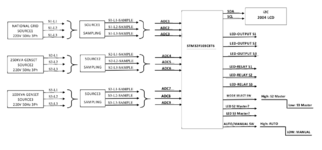
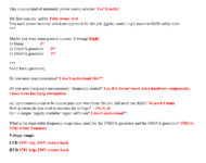
Please I want to know if one can really use some chips like AD736, AD737 and LTC1968 to read AC voltage?
For example my city grid if 220VAC nominal, Can I use these RMS to DC converter chips to really measure the input AC Voltage just as in AC Digital Voltmeter(1602 LCD) with Arduino?

Please I really need to confirm this
 

Ok
Hi,

Maybe I confused you with "too much details". In this case I want to apologise.

Maybe we rather should focus on the requirement that on the soution.
(This is necessary independent whether you design it on your own or you hire somebody)
If you want to hire somebody, you should do ths in the "Job" section (refer to this thread)

***
But let´s put the hardware and software aside for a moment. Not thinking about RMS and so on.

What do you want the "device" to do.
You said there are 3 x 3 phases. Where do they come from?
Tell us a bit about your system.

Klaus
Ok, I will post it when I get home. I'm on the go now.
 

An accuracy specification should be one of the design starting points. It answers the question if STM32 internal ADC accuracy is sufficient for the application or if you need an external ADC. If you plan a high performance application, you should also consider to use energy meter ICs as analog front end. They have outstanding accuracy and built-in RMS calculation.
 

Hi,
For example if an LED is attached to a digital pin instructed to go off when all the 3 lines of Source1 goes below/above a defined threshold the LED will delay some milliseconds before it goes off! In the application, the delay is not acceptable because Source2 needs to be snapped in without interrupting the supply to the load
"some milliseconds" ...This - on the other hand - sounds like the application is rather timing critical, maybe a true RMS calculation is the wrong way to go...

Klaus
 

I will prepare it to a very clear description when I get home
--- Updated ---

An accuracy specification should be one of the design starting points. It answers the question if STM32 internal ADC accuracy is sufficient for the application or if you need an external ADC. If you plan a high performance application, you should also consider to use energy meter ICs as analog front end. They have outstanding accuracy and built-in RMS calculation.
As part of one the things I want now from a paid developer is "consultancy" regarding component management. All will depend on when I post the full descriptions of my project here then the experts here will understand it and could be able to decide which components are the best for the application.
 
Last edited:

The thing I want is this: I write this in a hurry. I will honor any questions or correction I might have made somewhere in the description.
Thanks.
 

Attachments

  • AUTOMATIC ELECTRICAL PANEL.pdf
    127.3 KB · Views: 92
  • Descriptions.pdf
    91.3 KB · Views: 83

The thing I want is this: I write this in a hurry. I will honor any questions or correction I might have made somewhere in the description.
Thanks.
 

Attachments

  • Capture.PNG
    Capture.PNG
    85.9 KB · Views: 70

Hi,

this is some kind of automatic power source selector.

My first concern: safety
You need power switches which are approved for this job. lso the control logic needs to fulfill safety rules.
***

Maybe you want some priority (correct if wrong)
1) mains
2) 250kVA generator
3) 100kVA generator

***
Some basic questions:

Do you need synchronisation?

Do you need frequency measurement / frequency control?

All input sources seem to be almost pure sine waveform. Do you still need true RMS?
How accurate do you need to measure the voltage?
Isn´t a simple "supply available" signal sufficient?

What is the expectable frequency range (min, max) for the 250kVA generator and the 100kVA generator?

Klaus
 

Attachments

  • Edaboard Reply.PNG
    Edaboard Reply.PNG
    75.1 KB · Views: 72

Hi,

please answer as text. It´s hard to reply on a picture.

Synchronisation is essential when - for example - you connect a synchronous generator to the grid.
I´m quite soure you don´t want to connect the generator with the grid -- rather you should strictly avoid this.
Please confirm.

On the other hand it may be a benefit when frequency, maybe even phase is aligned before switching from one source to the other. But it is not essential.
How much blanking time do you expect (min/max)?

Frequency measurement: You need it, or it´s just nice to have?

Simple "supply available:"
A simple method could be to 3 phase rectify, ... no capacitor .. just check with a comparator that the voltage continously above a certain level. This is very simple, checks for three phases, booth polarities and a certain voltage level.
6 diodes, resistive divider, comparator, fast_OFF_slow_ON delay

If you have a little experience with Excel, then you can test it on your own. For sure almost any circuit simulator can do this, too.

Klaus
Ok I understand. Please I am sorry for the picture message.
  • I don't want Synchronization
  • I want to use frequency. It will be nice and look more mature project to display the frequency along with the voltage on the LCD
  • Simple "supply available...:unsure::unsure::unsure:. In this way it sounds good but, can the lines be able to displayed differently L1, L2and L3 on the LCD? Or will it display in 3-phase format (380V)
Thanks for your replies. I am even learning new thigs already.
 

Hi,
can the lines be able to displayed differently L1, L2and L3 on the LCD?
It´s not measuring as analog value.
It´s just a TRUE/FALSE signal that comes from a simple validation circuit for all 3 phases in common.
It´s simple but still reliable signal, with a fast_turn_to_false option.

For sure one can do a measurement of the rectified signal and "calculate back" to the RMS value.

Klaus
 

Hi,

It´s not measuring as analog value.
It´s just a TRUE/FALSE signal that comes from a simple validation circuit for all 3 phases in common.
It´s simple but still reliable signal, with a fast_turn_to_false option.

For sure one can do a measurement of the rectified signal and "calculate back" to the RMS value.

Klaus

Ok sir, thank you for your time all this while. Now I want this code in question measure the signals and control just the outputs then I will prefer to use a separate MCU for the display alone. I will use a separate circuit and code to display the parameters by myself. The separate MCU will run on its firmware so that I will have a very good and stable reading without minding the conversion time. I have no problems with that. Before this, I have measured AC parameters With ZMPT101B transformer. It have served me very well especially with its high voltage tolerance and isolation advantage. So if someone will help me do this now that person will leave LCD entirely out of it. See this new picture:
NEW.PNG

--- Updated ---

Ok sir, thank you for your time all this while. Now I want this code in question measure the signals and control just the outputs then I will prefer to use a separate MCU for the display alone. I will use a separate circuit and code to display the parameters by myself. The separate MCU will run on its firmware so that I will have a very good and stable reading without minding the conversion time. I have no problems with that. Before this, I have measured AC parameters With ZMPT101B transformer. It have served me very well especially with its high voltage tolerance and isolation advantage. So if someone will help me do this now that person will leave LCD entirely out of it. See this new picture:
In this way the system mode will reflect to physical pins so I can use them as inputs to the LCD MCU for mode control
  • int8 source1=1 (system=source1 mode):- output_high(pin_x)
  • int8 source2=0 :- output_low(pin_y)
  • int8 source3=0 :- output_low(pin_z)

  • int8 source1=0 :- output_low(pin_x)
  • int8 source2=1 (system=source2 mode):- output_high(pin_y)
  • int8 source3=0 :- output_low(pin_z)

  • int8 source1=0 :- output_low(pin_x)
  • int8 source2=0 :- output_low(pin_y)
  • int8 source3=1 (system=source3 mode):- output_high(pin_z)
 
Last edited:

Status
Not open for further replies.

Similar threads

Part and Inventory Search

Welcome to EDABoard.com

Sponsor

Back
Top