Continue to Site

Welcome to EDAboard.com

Welcome to our site! EDAboard.com is an international Electronics Discussion Forum focused on EDA software, circuits, schematics, books, theory, papers, asic, pld, 8051, DSP, Network, RF, Analog Design, PCB, Service Manuals... and a whole lot more! To participate you need to register. Registration is free. Click here to register now.

Problem in SIM900D and SIM500W

Status
Not open for further replies.

homermike

Junior Member level 3
Joined
Jul 31, 2010
Messages
25
Helped
4
Reputation
10
Reaction score
4
Trophy points
1,283
Location
Cebu Philippines
Activity points
1,485
A. SIM500W
- GPRS connection problem
- AT+CDNSCFG=? (not supported)
- AT+CSTT=? (not supported)
- AT+CISFR (not supported)
- AT+CSTT=? (not supported)
etc... and even CIPCLOSE and CIPSHUT are not also supported... all replied ERROR.. only AT+CGATT=1 replied OK for all the GPRS command set.
- CMGR,CMGS,CMGD,CMGF and etc. is working fine
- the project deadline is at near.. and a mass production will be done after completing all the features on the project....
- we tried SIM300D before and everything works fine... but when we buy more qty on the SIM300D, supplier told us that the model is no longer on the market or no longer in production.. so they suggested to use SIM500W and SIM900D instead.. so we bought around 500pcs of SIM500w..but encountered the problem...

======================================
B. SIM900D
- every connection was setup properly
- netlight has been functioning after PWRKEY
- serial communication problem
- AT commands has been sent but no reply at all..
- all baudrate settings has been tried but still no proper communication
- proper power supply
- proper data cable use (TTL232 to USB) with prolific driver

hoping for fast reply on this matter... if someone can help solve the problem


thanks and more power.. -michael
 

the SIM300D has an embedded TCP/IP stack but as far as I am aware the SIM500W does not - hence you get "not supported" errors

the SIM900D should work - sounds as though i is not communicating at all - does it reply to a simple AT<ENTER> command ? have you checked the Rx and Tx lines with an oscilloscope? have you connected the CTS, RTS, DTR and DSR lines?
if it communicates at all check the signal level?
 

Thanks for the reply:

for SIM500W
base on the DATASHEET and ATC of sim500W it does have TCP/IP stack. (files attached)
sorry for the first post i'v written (not supported) i'm just thinking it is not supported since it always replying "ERROR"...
even AT+CSTT=? and AT+CSTT? also replied error so also AT+CSTT="www.globe.com.ph","globe",globe" will reply ERROR

for SIM900D
even a simple AT<ENTER> the module really doesn't reply...
we use same data cable in controlling sim500w and sim300D so supposedly the cable will work on sim900D
CTS, RTS, DTR and DSR lines is not connected..just a simple RX/TX/GND line is connected..since it is working in sim500w and sim300D
we'v tried as of now 4pcs sim900D modules and all modules we failed to communicate with it...

thanks...
 

Attachments

  • SIM500W&SIM540W_HD_V1.01.pdf
    1.9 MB · Views: 133
  • SIM500W_ATC_V1.00.pdf
    1.1 MB · Views: 119

what does the SOM500W report to signal quality AT+CSQ and network registration AT+CREG ?

for the SIM900D try connecting CTS to RTS and DTR to DSR
I assume you have tried all the standard baud rates 2400, 4800, 9600, 14400, 19200, 38400 57600 and 115200
 

thanks for the reply...

for SIM500W sim1: CSQ=13% sim2: CSQ=26%

for sim900D:
yes..been tried all the baudrates.. then i will try what u suggest now...
big thanks...
 

try reading the SIM500W firmware version then email the manufacturers to check it is TCP/IP enabled.
I have been given modems before now that were supposed to have a TCP/IP stack to find it was not included in the installed firmware (had to throw away expensive PCBs!)

have you had a look at
www.mt-system.ru/documents/sim900d_hd_v1.02.pdf
 
Last edited:

for sim500w
PL0824B05SIM500W32_ESMT_V301_FCT_TAIF - this is the firmware version after issuing AT+CGMR command...
inquiry been sent to the manufacturer and supplier if the the version supports TCP/IP stack
 

for sim900D


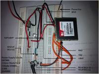
- Power supply is 12vdc 2A
- regulated by 7805 to convert the voltage down to 5v
- with zener and 1N4001 diode in series to get the voltage down to 3.6v
- then connected to SIM900D VBAT pin and with GND also
*now power supply for sim900D is setup and OK
- 1 LED for the NETLIGHT
- RX of sim900D is connected to the TX of DCU-11 data cable
- TX of sim900D is connected to the RX of DCU-11 data cable
- GND of DCU 11 cable is connected to the GND of sim900D
* now serial communication is setup and OK (we'v used this setup for SIM500w and sim300D and working fine)
- we connect PowerKey to the GND for 2sec and NETLIGHT LED starting to BLINK fast (since no simcard)
- supposdly we should see "RDY" "CFUN" "CPIN" and etc... to the SERIAL TERMINAL Software but we havn't (like what sim500w and sim300d does)
- we send "AT" and "ENTER", "OK" is expected but we receive garbage...
- then we try changing the baudrate but same thing happened (all baudrate available has been tested)
* now we tried the suggestion to connect RTS to CTS and DTR to DCD
- CTS Connected to RTS = Data Sent equals Data Received and mostly garbage
- CTS Connected to RTS and DTR Pulled Up = Data Sent equals Data Received and Continuous Reply of Blank Data
- CTS Connected to RTS and DTR Pulled Down = Data Sent equals Data Received
- CTS Connected to RTS and DTR Connected to DCD = No Reply

* we tried 4pcs of sim900D module and all has just same behavior.., is there any lacking method we missed?
kindly tell us what we need to do just to communicate with the module...

thanks...
 

the fact that you are getting garbage sounds like baudrate error (but you have checked all these) or corrupt signals - have you connected to the correct ground on the SIM900D ? noise on the Tx and Rx lines ? have you looked at the Tx and Rx signals using an oscilloscope?

this one any help?
**broken link removed**
 

for sim900D


- Power supply is 12vdc 2A
- regulated by 7805 to convert the voltage down to 5v
- with zener and 1N4001 diode in series to get the voltage down to 3.6v
- then connected to SIM900D VBAT pin and with GND also
*now power supply for sim900D is setup and OK
- 1 LED for the NETLIGHT
- RX of sim900D is connected to the TX of DCU-11 data cable
- TX of sim900D is connected to the RX of DCU-11 data cable
- GND of DCU 11 cable is connected to the GND of sim900D
* now serial communication is setup and OK (we'v used this setup for SIM500w and sim300D and working fine)
- we connect PowerKey to the GND for 2sec and NETLIGHT LED starting to BLINK fast (since no simcard)
- supposdly we should see "RDY" "CFUN" "CPIN" and etc... to the SERIAL TERMINAL Software but we havn't (like what sim500w and sim300d does)
- we send "AT" and "ENTER", "OK" is expected but we receive garbage...
- then we try changing the baudrate but same thing happened (all baudrate available has been tested)
* now we tried the suggestion to connect RTS to CTS and DTR to DCD
- CTS Connected to RTS = Data Sent equals Data Received and mostly garbage
- CTS Connected to RTS and DTR Pulled Up = Data Sent equals Data Received and Continuous Reply of Blank Data
- CTS Connected to RTS and DTR Pulled Down = Data Sent equals Data Received
- CTS Connected to RTS and DTR Connected to DCD = No Reply

* we tried 4pcs of sim900D module and all has just same behavior.., is there any lacking method we missed?
kindly tell us what we need to do just to communicate with the module...

thanks...


Sir if i used 9 V 400 mA.i split the current into two. one for atmega arduino to supply 9 V and the other is that i used 7805 to regulate into 5 V. the GSM module did not work. can you help for this matter. what should i do tnx?
 

it should work, u must have a diode in between 5VDC and VBAT of the GSM... so that it will drop 0.7v... GSM module only requires 3.3v to 4.8v...
have u tried to connect GND to the PWRKEY Pin for a few seconds?
thats the procedure on how to turn on the GSM module... also connect 1 LED to the NETWORK PIN... + PIN of LED connect it to the NETWORK PIN of the MODULE and - PIN of LED connect to GND...

after u connect the PWRKEY PIN of the module to GND in few seconds.. u should see the LED blinking... if it does... then the module is alive..

then proceed in interfacing the SIMCARD socket and rest of the connections e.g. SERIAL pin part...
 
Capacitor of a considerably better value (e.g. 100uF, 10V or similar) needs to be soldered very close to VBAT & GND pins of the GSM Module.
 

Status
Not open for further replies.

Part and Inventory Search

Welcome to EDABoard.com

Sponsor

Back
Top