Continue to Site

Welcome to EDAboard.com

Welcome to our site! EDAboard.com is an international Electronics Discussion Forum focused on EDA software, circuits, schematics, books, theory, papers, asic, pld, 8051, DSP, Network, RF, Analog Design, PCB, Service Manuals... and a whole lot more! To participate you need to register. Registration is free. Click here to register now.

18S20 Parastic power mode

Status
Not open for further replies.

cubanflyer

Full Member level 5
Joined
Jul 31, 2010
Messages
255
Helped
75
Reputation
152
Reaction score
71
Trophy points
1,308
Location
UK
Activity points
2,500
Hi

I am looking at using multiple 18s20 devices in a monitoring unit, I was thinking of using parastic power for the device.

Has any one used this mode?
Is so make what is the max cable distance used ?
What number of devices?

Thanks
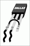
 

I use lots parasitic mode on 1-wire. I use few DS18B20, up to five-six max in parasite mode, lots a times. Wires length is about 10m UTP CAT6. Even DS2408 go in parasite mode.

The 1-Wire bus system uses a single bus master to control one or more slave devices. The DS18B20-PAR is always a slave. When there is only one slave on the bus, the system is referred to as a “singledrop” system; the system is multi-drop” if there are multiple slaves on the bus. All data and commands are transmitted least significant bit first over the 1-Wire bus. The following discussion of the 1-Wire bus system is broken down into three topics: hardware configuration, transaction sequence, and 1-Wire signaling (signal types and timing).


203Fig02.gif


Page 5 in AN148 Guidelines for Reliable Long Line 1-Wire® Networks.pdf
Parasite Powering Issues
The 1-Wire waveform must not only be sufficient for communication, but also provide operating power for the slaves. Each slave "robs" power from the bus when the voltage on the bus is greater than the voltage on its internal energy storage capacitor. When the weight of the network becomes excessive, the current delivered by the master may not be sufficient to maintain operating voltage in the slaves. The worst-case scenario for parasite power is a very long sequence of zero bits issued by the master. When this occurs, the line spends most of its time in the low state, and there is very little opportunity to recharge the slaves. If the bus reaches a sufficient voltage during the recovery time between bits and if the recovery time is long enough, there is no problem. As the internal operating voltage in each slave drops, the slave's ability to drive the bus to make zero bits is reduced, and the timing of the slave changes. Eventually, when the parasite voltage drops below a critical level, the slave enters a reset state and stops responding. Then, when the slave again receives sufficient operating voltage, it will issue a presence pulse and may corrupt other bus activity in doing so. When a network has insufficient energy to maintain operating power in the slaves, failures will be datadependent and intermittent.
 

Attachments

  • DS18S20-PAR.pdf
    250.4 KB · Views: 40
  • AN148 Guidelines for Reliable Long Line 1-Wire® Networks.pdf
    225.9 KB · Views: 40
Last edited:
Status
Not open for further replies.

Part and Inventory Search

Welcome to EDABoard.com

Sponsor

Back
Top