TheFallenAngel
Newbie level 3
Hello,can I write the control command in C if the boot loader in pic18f4550 is in assembly language?thank you.
Follow along with the video below to see how to install our site as a web app on your home screen.
Note: This feature may not be available in some browsers.
abidr,
Ok. May i know what is the difference between both type of bootloader ?
Do you have the download sources for the PICDEM ?
PICDEM = picdemfsusb.hex ?
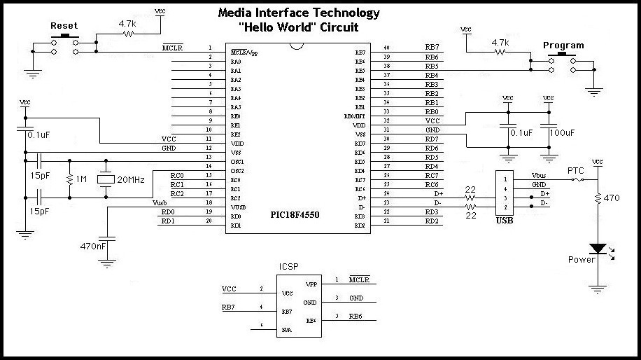
Any reference of the circuits you used for your PIC ?
Why we need to ground the RC6 ?
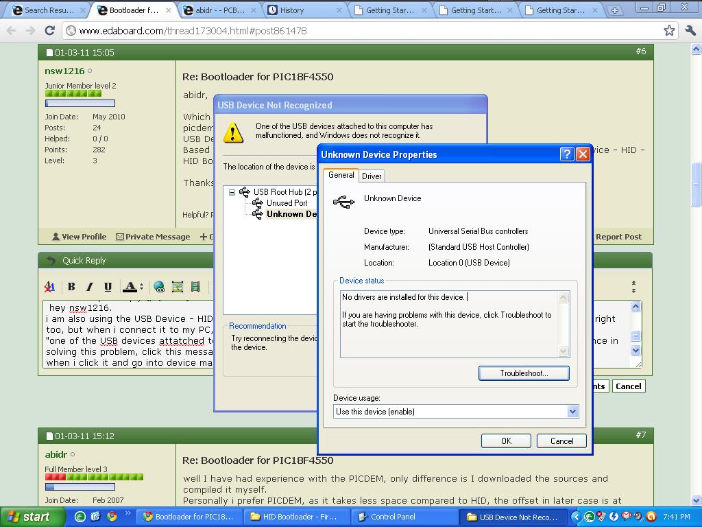
But with the HID bootloader my PC cant detect my device ? WHy ?
About the tutorial you stated above, it is under which topic ?
There was another issue with the bootloaders, once you program it in the mcu the bootloader button is at RB4, but after uploading the main program the bootloader button shifted to RC6.

hey nsw1216.abidr,
Which hex file do you used for the bootloader ?
picdemfsusb.hex?
USB Device - HID - HID Bootloader - C18 - PIC18F4550.hex?
Based on my circuit, the push button switch is at RB4 not RC6 and i am using the USB Device - HID - HID Bootloader - C18 - PIC18F4550.hex for my bootloader.
Thanks for your reply.
")
any ideas??but then, i have been wondering if i will have to make
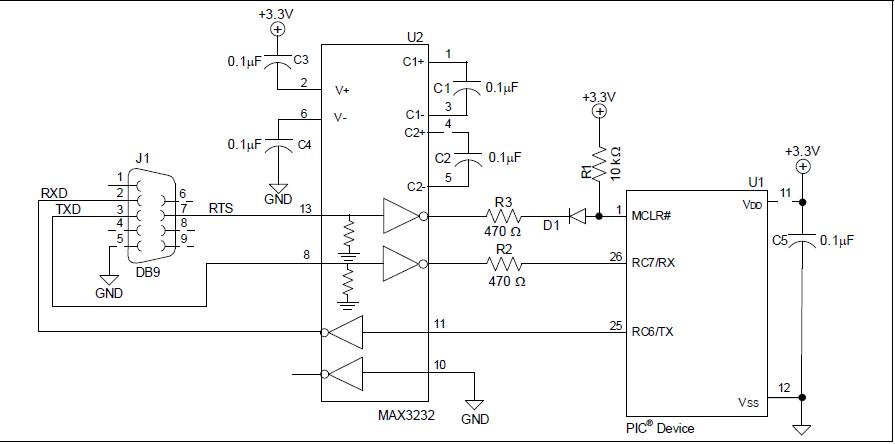
this circuit to use the serial AN1310 bootloader.... and if so, how do i get that +3.3V supply? can i use a voltage regulator (12V-to-3.3V) directly on the RS232 +12V supply? ( RS232 is completely new to me)