darkfall94
Newbie level 6

- Joined
- Nov 8, 2014
- Messages
- 13
- Helped
- 0
- Reputation
- 0
- Reaction score
- 0
- Trophy points
- 1
- Activity points
- 126
Hello,
My project is interfacing a keypad & LCD with microcontroller i.e i press the button on my keypad and the LCD displays the number and number of times the key is pressed.
If you see the above code,it uses a header file lcd.h
The code for the header file is:
The only change i made is connect pin 3 of lcd i.e vee to +VCC=5V due to unavailability of a potentiometer.
I simulated the circuit with the code on Proteus software and it works like a charm--perfect!
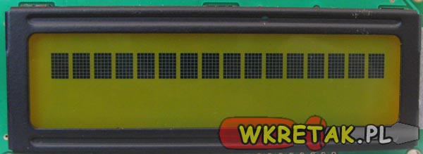
but now when i supply power to circuit, the lcd displays black boxes..
lcd is jhd162a
here's the link for its datasheet:
http://www.itron.com.cn/PDF_file/JHD162A%20SERIES.pdf
i gave pin16 of lcd gnd and pin15 VCC for the backlight.
what could be the problem?
My project is interfacing a keypad & LCD with microcontroller i.e i press the button on my keypad and the LCD displays the number and number of times the key is pressed.
If you see the above code,it uses a header file lcd.h
The code for the header file is:
Code dot - [expand]
The only change i made is connect pin 3 of lcd i.e vee to +VCC=5V due to unavailability of a potentiometer.
I simulated the circuit with the code on Proteus software and it works like a charm--perfect!
but now when i supply power to circuit, the lcd displays black boxes..
lcd is jhd162a
here's the link for its datasheet:
http://www.itron.com.cn/PDF_file/JHD162A%20SERIES.pdf
i gave pin16 of lcd gnd and pin15 VCC for the backlight.
what could be the problem?
Last edited by a moderator: