Continue to Site

Welcome to EDAboard.com

Welcome to our site! EDAboard.com is an international Electronics Discussion Forum focused on EDA software, circuits, schematics, books, theory, papers, asic, pld, 8051, DSP, Network, RF, Analog Design, PCB, Service Manuals... and a whole lot more! To participate you need to register. Registration is free. Click here to register now.

[SOLVED] 16F887 with LM35DZ (measurement of positive temp only)

Status
Not open for further replies.

Eric_O

Advanced Member level 4
Joined
May 31, 2020
Messages
104
Helped
0
Reputation
0
Reaction score
0
Trophy points
16
Activity points
996
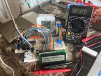
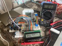
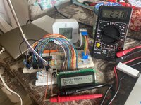
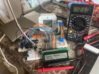
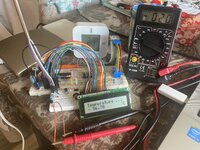
When measuring room temperature (approximatively between 21°C to 25°C) with PIC 16F887 and LM35DZ, LCD displays a room temperature of 100°C when room temperature is 21°C.

LM35 GND (pin 3) : connected to GND of MCU.
LM35 output (pin 2) : connected to ADC 3 of MCU and also to VCC thru a 2.2 K resistor.
LM35 output (pin 1) : not connected (instead of connected to VCC in some cases)

Regarding the datasheet of LM35 I wrote the code as follow and respected the math formulas.

Code:
void main()
{
 PORTB = 0;                                                 // Initialisation du PORT B à 0.
 PORTC = 0;                                                 // Initialisation du PORT C à 0.
 PORTD = 0;                                                 // Initialisation du PORT D à 0.

 ANSEL = 0b00001000;                                        // b3 = 1 (ANS3) : sets pin 5 (AN3) as analog input.
 ANSELH = 0b00000000;

 TRISB = 0b00000000;                                        // PORT B : b0 à b7 configurés en sortie.
 TRISC = 0b00000000;                                        // PORT C : b0 à b7 configurés en sortie.
 TRISD = 0b00000000;                                        // PORT D : b0 à b7 configurés en sortie.

 C1ON_bit = 0;                                              // CMC1CON register > b7 > C1ON bit = 0 > Disable comparator 1.
 C2ON_bit = 0;                                              // CMC2CON register > b7 > C1ON bit = 0 > Disable comparator 2.

 SCS_bit = 0;                                               // OSCCON register > b0 > SCS bit = 0 > External oscillator (quartz) is used as a clock source.

 LCD_Init_v4 (void);

 pointeur_de_char = &texte[0];                              // pointeur_de_char pointe sur le premier élément du tableau "texte", soit texte[0].
                                                            // Autrement dit, pointeur_de_char contient l'adresse (&) de texte[0].
 do
  {
   float adc;
   float volt, temp;

   char txt[13];

   ADC_initialization();

   TRISD = 0x00;

    while(1)
    {
     adc = (ADC_read(3));                                   // Reads analog values.
     volt = adc * 4.88281;                                  // Converts it into the voltage.
     temp = volt / 10.0;                                    // Gets the temperature values.
     temp = temp - 273;                                     // Converts Farenheit to Celcius.

     StrConstRamCpy(pointeur_de_char, "Temperature ...  "); // OK.
     LCD_Write_String_At(0, 0, pointeur_de_char);           // OK. Voir dans void LCD_Write_String(char *msg), le while(*(msg + k) > 0).

     float2ascii_v2(temp, &txt[0], 2);

     LCD_Write_String_At(1, 0, &txt[0]);                    // Write txt in 2nd row, starting at 1st digit.
     LCD_Write_String_At(1, 13, " °C");                     // Write " °C" in 2nd row, starting at 14th digit.

     delay_ms(3000);
    }
  }
 while(1);
}

Could somebody explain me why the displayed temperature is so inconsistent ?

Thanks !
 

LM35 GND (pin 3) : connected to GND of MCU.
LM35 output (pin 2) : connected to ADC 3 of MCU and also to VCC thru a 2.2 K resistor.
LM35 output (pin 1) : Vcc= 4~20V not connected (instead of connected to VCC in some cases)
Tony

0.0 to 1.0V = 0 to 100'C

Fix: Connect Vcc , remove R , verify Output with Vdc on a DMM and verify each pin always then code!
 

Also move these out of the 'do' loop, they only need defining once.
float adc;
float volt, temp;
char txt[13];

I don't have the data sheet with me at the moment but the conversion of Fahrenheit to Celsius looks very wrong to me. From my memory the LM35 output is 10mV/C so it doesn't need converting at all.

Try disconnecting the output from the LM35 and instead connect a potentiometer across VCC and Ground with its slider connected to the ADC. As you turn it you should see the temperature go from one end to the other of its scale. If it doesn't, the results should give some clues about why it isn't working. Don't forget you have a 3 second delay in your loop so the reading will be slow to respond.

Brian.
 

Dear Brian,
Here under my code ... While running, temperature displayed on LCD start from a negative value a increase to 3 or 4°C ... No more. While room temp is around 20°C now.
Code:
void main()
{
 PORTB = 0;                                                 // Initialisation du PORT B à 0.
 PORTC = 0;                                                 // Initialisation du PORT C à 0.
 PORTD = 0;                                                 // Initialisation du PORT D à 0.

 ANSEL = 0b00011000;                                        // b3 = 1 (ANS3) : sets pin 5 (AN3) as analog input.
                                                            // b4 = 1 (ANS4) : sets pin 7 (AN4) as analog input.
 //Or
 //ANSEL = 24;
 ANSELH = 0b00000000;

 TRISB = 0b00000000;                                        // PORT B : b0 à b7 configurés en sortie.
 TRISC = 0b00000000;                                        // PORT C : b0 à b7 configurés en sortie.
 TRISD = 0b00000000;                                        // PORT D : b0 à b7 configurés en sortie.

 C1ON_bit = 0;                                              // CMC1CON register > b7 > C1ON bit = 0 > Disable comparator 1.
 C2ON_bit = 0;                                              // CMC2CON register > b7 > C1ON bit = 0 > Disable comparator 2.

 SCS_bit = 0;                                               // OSCCON register > b0 > SCS bit = 0 > External oscillator (quartz) is used as a clock source.

 LCD_Init_v4 (void);

 pointeur_de_char = &texte[0];                              // pointeur_de_char pointe sur le premier élément du tableau "texte", soit texte[0].
                                                            // Autrement dit, pointeur_de_char contient l'adresse (&) de texte[0].
 do
  {
   int voltage_at_Vout_pin, voltage_at_GND_pin;
   float temp;

   char txt[13];

   ADC_initialization();

   TRISD = 0x00;

    while(1)
    {
     voltage_at_Vout_pin = ADC_read(3);                           // Reads analog voltage at Vout pin of LM35DZ.
     voltage_at_GND_pin = ADC_read(4);                            // Reads analog voltage at GND pin of LM35DZ.

     temp = (voltage_at_Vout_pin - voltage_at_GND_pin) * 4.888;   // Reads analog voltage and converts it to Celsius degrees (4.888 = 5000 mV / 1023). 5000 mV = 5V = VCC of MCU.
     temp = temp / 10;                                            // With LM35, each 10 mV output correspond to 1°C.

     StrConstRamCpy(pointeur_de_char, "Temperature ...  ");       // OK.
     LCD_Write_String_At(0, 0, pointeur_de_char);                 // OK. Voir dans void LCD_Write_String(char *msg), le while(*(msg + k) > 0).

     //float2ascii_v1(temp, &txt[0], 2);
     float2ascii_v2(temp, &txt[0], 2);

     LCD_Write_String_At(1, 0, &txt[0]);                          // Write txt in 2nd row, starting at 1st digit.
     LCD_Write_String_At(1, 13, " °C");                           // Write " °C" in 2nd row, starting at 14th digit.

     delay_ms(3000);
    }
  }
 while(1);
}

Thanks for enlighten me.

Eric

Tony

0.0 to 1.0V = 0 to 100'C

Fix: Connect Vcc , remove R , verify Output with Vdc on a DMM and verify each pin always then code!
I did all, except check Vout with a DMM or oscillo.
--- Updated ---

Also move these out of the 'do' loop, they only need defining once.
float adc;
float volt, temp;
char txt[13];

I don't have the data sheet with me at the moment but the conversion of Fahrenheit to Celsius looks very wrong to me. From my memory the LM35 output is 10mV/C so it doesn't need converting at all.

Try disconnecting the output from the LM35 and instead connect a potentiometer across VCC and Ground with its slider connected to the ADC. As you turn it you should see the temperature go from one end to the other of its scale. If it doesn't, the results should give some clues about why it isn't working. Don't forget you have a 3 second delay in your loop so the reading will be slow to respond.

Brian.
Thanks !
I removed these lines in my last code here below.
You're are right, connecting a potentiometer is the smarter way. Will do that.
--- Updated ---

What is the code in 'ADC_initialization()' as that will determine how the values are being represented in the 'Voltage_at_...' variables. Ditto the code in 'ADC_read()'.
Have you tried to debug the code?
In particular what are the values that you have in the 'Voltage_at_...' variables? If they are not right then your calculations are somewhat meaningless.
Susan
Will monitor the different variables with the MikroE Debugger.
 
Last edited:

I did all, except check Vout with a DMM or oscillo.
--- Updated ---


Thanks !
I removed these lines in my last code here below.
You're are right, connecting a potentiometer is the smarter way. Will do that.
--- Updated ---


Will monitor the different variables with the MikroE Debugger.
Dear Susan,
Here under are both subroutines for ADC :

Code:
void ADC_initialization()
{
 ADCON0 = 0b01000001;
 ADCON1 = 0b10000000;           
}

unsigned int ADC_read(unsigned char channel)
{
 static unsigned int k;
 ADCON0 = ADCON0 & 0b11000011;
 channel = channel << 2;
 ADCON0 = ADCON0 | channel;
 Delay_ms(2);
 ADCON0.GO_DONE = 1;
 _asm NOP;
 while (ADCON0.GO_DONE == 1);
 {
  k = ADRESL + (ADRESH * 256);
 }
 return(k);
}

🤔
 

Hi,

your code reads the conversion result many times in a loop while the conversion is still in process..

try this:

Code:
while (ADCON0.GO_DONE == 1);
 {  }             // wait for conversion to become finished
 k = ADRESL + (ADRESH * 256);          // finíshed, now read the ADConversion result
 return(k);
 

    Eric_O

    Points: 2
    Helpful Answer Positive Rating
You might also need to add a cast like this:
k = (unsigned int)ADRESL + (unsigned int)(ADRESH * 256);
the reason being that both ADC results are probably of 'char' type.

Not sure why you make 'k' a static variable but never use its previous value.

Brian.
 

    Eric_O

    Points: 2
    Helpful Answer Positive Rating
then at least check with DMM for 220 mV at 22'C
Merci !
I did that. When room temperature is 23°C, voltage between Vout (pin 2) and GND (pin 3) of LM35 is 230 mV … But when displayed temp on LCD change every 5 sec (due to the delay in my code) as shown on attached pics, temp is consistent only once every four samplings.
😕🤔
--- Updated ---

You might also need to add a cast like this:
k = (unsigned int)ADRESL + (unsigned int)(ADRESH * 256);
the reason being that both ADC results are probably of 'char' type.

Not sure why you make 'k' a static variable but never use its previous value.

Brian.
Merci !
I make correction. When room temperature is 23°C, voltage between Vout (pin 2) and GND (pin 3) of LM35DZ is almost 0 mV always … And displayed temp on LCD that change every 5 sec (due to the delay in my code) never exceed 2 degrees as shown on attached pics,
😕🤔
--- Updated ---

Merci !
I did that. When room temperature is 23°C, voltage between Vout (pin 2) and GND (pin 3) of LM35 is 230 mV … But when displayed temp on LCD change every 5 sec (due to the delay in my code) as shown on attached pics, temp is consistent only once every four samplings.
😕🤔
--- Updated ---

You might also need to add a cast like this:
k = (unsigned int)ADRESL + (unsigned int)(ADRESH * 256);
the reason being that both ADC results are probably of 'char' type.

Not sure why you make 'k' a static variable but never use its previous value.

Brian.

Merci !
I make correction. When room temperature is 23°C, voltage between Vout (pin 2) and GND (pin 3) of LM35DZ is almost 0 mV always … And displayed temp on LCD that change every 5 sec (due to the delay in my code) never exceed 2 degrees as shown on attached pics,
😕🤔
 

Attachments

  • E363391D-F48A-4946-9C57-F237D7BEF35C.jpeg
    E363391D-F48A-4946-9C57-F237D7BEF35C.jpeg
    3.6 MB · Views: 47
  • 2625122C-4C44-4508-97D5-B94CE8106076.jpeg
    2625122C-4C44-4508-97D5-B94CE8106076.jpeg
    3.6 MB · Views: 61
  • 62D972CF-FB06-4057-8F6E-BCF158EB92EB.jpeg
    62D972CF-FB06-4057-8F6E-BCF158EB92EB.jpeg
    3.6 MB · Views: 49
  • AD3B73F5-C0F1-46DB-A8A6-AD66D9EB0BA0.jpeg
    AD3B73F5-C0F1-46DB-A8A6-AD66D9EB0BA0.jpeg
    3.6 MB · Views: 53
  • F29C91CC-65CF-44FC-9C02-6A0D0844514C.jpeg
    F29C91CC-65CF-44FC-9C02-6A0D0844514C.jpeg
    2 MB · Views: 46
  • 46C48996-B032-4B64-80B0-35BE7CE0E9F1.jpeg
    46C48996-B032-4B64-80B0-35BE7CE0E9F1.jpeg
    2 MB · Views: 52
  • FDE0AB81-C9A1-4351-A305-EEE69003BA5B.jpeg
    FDE0AB81-C9A1-4351-A305-EEE69003BA5B.jpeg
    2 MB · Views: 47
  • CB55C2ED-0FC5-4A7B-B764-540DEDAA3C96.jpeg
    CB55C2ED-0FC5-4A7B-B764-540DEDAA3C96.jpeg
    2 MB · Views: 54
  • 3A321F3E-FFF0-4705-86F4-B6276AF4D4E0.jpeg
    3A321F3E-FFF0-4705-86F4-B6276AF4D4E0.jpeg
    2 MB · Views: 51
  • D7148612-3AC0-498E-8903-37BAFB359076.jpeg
    D7148612-3AC0-498E-8903-37BAFB359076.jpeg
    2 MB · Views: 41
  • B7D987D0-C5D7-4E07-9F2B-4C621ACF6F35.jpeg
    B7D987D0-C5D7-4E07-9F2B-4C621ACF6F35.jpeg
    2 MB · Views: 53
Last edited:

Hi, your code reads the conversion result many times in a loop while the conversion is still in process.. try this:
Code:
while (ADCON0.GO_DONE == 1); { } // wait for conversion to become finished k = ADRESL + (ADRESH * 256); // finíshed, now read the ADConversion result return(k);
Hi,

your code reads the conversion result many times in a loop while the conversion is still in process..

try this:

Code:
while (ADCON0.GO_DONE == 1);
 {  }             // wait for conversion to become finished
 k = ADRESL + (ADRESH * 256);          // finíshed, now read the ADConversion result
 return(k);
Thank’s.
I did correction.
👍🏻
Hi,

your code reads the conversion result many times in a loop while the conversion is still in process..

try this:

Code:
while (ADCON0.GO_DONE == 1);
 {  }             // wait for conversion to become finished
 k = ADRESL + (ADRESH * 256);          // finíshed, now read the ADConversion result
 return(k);
Thank you for this smart remark. I make correction.
 

Merci !
I did that. When room temperature is 23°C, voltage between Vout (pin 2) and GND (pin 3) of LM35 is 230 mV … But when displayed temp on LCD change every 5 sec (due to the delay in my code) as shown on attached pics, temp is consistent only once every four samplings.
😕🤔
--- Updated ---


Merci !
I make correction. When room temperature is 23°C, voltage between Vout (pin 2) and GND (pin 3) of LM35DZ is almost 0 mV always … And displayed temp on LCD that change every 5 sec (due to the delay in my code) never exceed 2 degrees as shown on attached pics,
😕🤔
--- Updated ---


--- Updated ---


Merci !
I make correction. When room temperature is 23°C, voltage between Vout (pin 2) and GND (pin 3) of LM35DZ is almost 0 mV always … And displayed temp on LCD that change every 5 sec (due to the delay in my code) never exceed 2 degrees as shown on attached pics,
😕🤔
Do some body have an idea, concerning my problem ? Thanks 🙏🏻
 

Show us your latest code please.
Also, disconnect the LM35 and replace it with a potentiometer temporarily. Connect it between 0V and VDD with the wiper to the analog input of the PIC. Now adjust the potentiometer and tell us what the LCD says with different voltages on the wiper. I suggest telling us the reading every 0.25V between 0V and 5V.

What I am trying to establish is whether there is an electrical problem or a code problem, providing the voltage from a potentiometer will make it easy to tell which it is and it will give clues about problems in the way the voltage is converted to a temperature.

Brian.
 

Hi,

You´re no newbie here. You should know how it works.

Asking for help requires some informations
* Schematic, code ....
* how you tested it (test conditions)
* tell what you expect to see
* tell what you see instead

Btw: I don´t react on those multi megabytes of pictures that could simply be reduced to some 10s of kilobytes without losing thread related informations. It simply takes me too long to download them.

It should be your interest to make helping easy.

Klaus
 

Do some body have an idea, concerning my problem ? Thanks 🙏🏻
Dear Brian,

Regarding your advices, here under is the table of measurements values and the code in the attached file :

Almost for each voltage value set every 0,25 V with potentiometer (values displayed on Multimeter > first column), voltages values dispayed on LCD (second column) switch to several close values, with a step of 0,50 mV and loop. Most of the time one or two of the middle values in the list, appears most frequently.

Multimeter (V)LCD (mV)
0.021.96, 2.44, 2.93, 3.42, 3.91, 4.89
0.2524.93, 25.42, 25.91, 26.40, 26.88, 27.37, 27.86
0.5050.35, 50.84, 51.32, 51.81, 52.30, 52.79
0.7574.79, 75.28, 75.76, 76.25, 76.74, 77.23
1.00100.20, 100.69, 101.18, 101.67, 102.16, 102.65
1.25125.62, 126.11, 126.60, 127.09, 127.60
1.50150.55, 151.04, 151.53, 152.02, 152.51
1.75175.48, 175.97, 176.46, 176.95
2.00200.90, 201.39, 201.87, 202.36
2.25225.83, 226.31, 226.80
2.50251.24, 251.73, 252.22, 252,71
2.75276.17, 276.66, 277.15
3.00301.10, 301.59, 302.08
3.25326.52, 327.01
3.50351.94, 352.42
3.75377.35, 376.86
4.00402.28, 402.77
4.25427.21, 427.70
4.50452.14, 452.63
4.75477.07, 477.56, 478.05
4.96498.58, 499.06, 499.55

Thanks.

Eric
 

Attachments

  • Thermometer_with_LM35_and_LCD_v7_edaboard.zip
    4.3 KB · Views: 59

You have a factor of 10 difference, is that scope measurement and your probe setting
wrong ?

Regards, Dana.
 

You have a factor of 10 difference, is that scope measurement and your probe setting
wrong ?

Regards, Dana.
LM35 is 10 mV/deg C
--- Updated ---

Dear Brian,

Regarding your advices, here under is the table of measurements values and the code in the attached file :

Almost for each voltage value set every 0,25 V with potentiometer (values displayed on Multimeter > first column), voltages values dispayed on LCD (second column) switch to several close values, with a step of 0,50 mV and loop. Most of the time one or two of the middle values in the list, appears most frequently.

Multimeter (V)LCD (mV)
0.021.96, 2.44, 2.93, 3.42, 3.91, 4.89
0.2524.93, 25.42, 25.91, 26.40, 26.88, 27.37, 27.86
0.5050.35, 50.84, 51.32, 51.81, 52.30, 52.79
0.7574.79, 75.28, 75.76, 76.25, 76.74, 77.23
1.00100.20, 100.69, 101.18, 101.67, 102.16, 102.65
1.25125.62, 126.11, 126.60, 127.09, 127.60
1.50150.55, 151.04, 151.53, 152.02, 152.51
1.75175.48, 175.97, 176.46, 176.95
2.00200.90, 201.39, 201.87, 202.36
2.25225.83, 226.31, 226.80
2.50251.24, 251.73, 252.22, 252,71
2.75276.17, 276.66, 277.15
3.00301.10, 301.59, 302.08
3.25326.52, 327.01
3.50351.94, 352.42
3.75377.35, 376.86
4.00402.28, 402.77
4.25427.21, 427.70
4.50452.14, 452.63
4.75477.07, 477.56, 478.05
4.96498.58, 499.06, 499.55

Thanks.

Eric
Your display shows five significant figures yet your resolution is two of them, which is 0.49. This means you should be rounding off or you could add noise and average.

The readings in the middle of the string that repeat most often are the ones that are closer to the mean, unlike the peaks, which have noise. If the noise is random then deviation will reduce by the square root of the number of samples. If there is noise on your Vref or Gnd reference, used by the ADC, then there may be dead spots near the transitions of 0.49 or binary multiples of that.

I would test this with a slow ramp or triangular sweep, and then take the difference between the input and the output voltage using the ADC-DAC.
But you should consider averaging and truncate to 0.1 deg or nearest 0.25deg for more meaningful uncertainty.
 
Last edited:

You have a factor of 10 difference, is that scope measurement and your probe setting
wrong ?


Actually what I stated not clearly is this is in reference to his multimeter versus what he displays on LCD
the 10X difference.....

Regards, Dana.
 

Thee is certainly a noise and resolution problem but I suspect the real issue is simply the small range of voltages from the LM35. The ADC input voltage and the LCD reading are in accord, aside from possibly being scaled by 10 so the ADC itself seems to be working OK. However if the LM35 is only measuring a limited range of temperature, the voltage it will produce is being lost in the resolution. Most of the ADC range is beyond what the LM35 can produce, even at high temperature.

There are two solutions, one is to amplify the output voltage of the LM35 so it covers more of the ADC range, the other is to reduce the ADC's Vref to expand its scale. Both require additional circuitry and both introduce new problems of their own.

Something puzzles me, in the photographs the test meter is presumably measuring the voltage at the LM35 output but the range selector knob seems to be set to the 200mA current range, perhaps it is just the camera angle.

Personally, I would consider replacing the LM35 with an MCP9701A, they have a wider temperature range and the output is optimized for an ADC to read. You do have to subtract a voltage measurement to set 0C but that's unavoidable if measuring negative temperatures. I've used lots of them very successfully, I put them in my fridge alongside a calibrated thermometer for 30 minutes then measure the output voltage to get the exact offset voltage to use for high accuracy.

Brian.
 

    Eric_O

    Points: 2
    Helpful Answer Positive Rating
Quantization errors do not round up easily.

I suggest adjust/calibrate Vcc to 5.115 Vdc then
millivolts = adc * 5.000;
temp = millivolts / 10.0

Then use a rolling average of values and truncate to 3 or 4 digits.
The LM35 accuracy is 0.5 'C max at 25'C and the linearity error is 1% max.

More than 3 digits are irrelevant

unless you have a rolling average of 100 readings to improve accuracy x10 or 1 more digit with added analog random noise.
--- Updated ---

LM35 output but the range selector knob seems to be set to the 200mA current range, perhaps it is just the camera angle.

Brian.
wrong pointer
 

Hello Leo,

Probleme in your code in Thermometer_with_LM35_and_LCD_v7_edaboard.c
char txt[13]; is too short..
if overflow of txt table, you can get somme strange behavior or a MCU reset !
with a 16chars wide LCD , you must use a minimum of 17 bytes
so char txt[17];
in case of using a string of 16chars ( with Zero terminator, means 17 bytes long) !
For safety usage you can add *(txt+16)=0; before sending to LCD

and is not usual to put variable init inside a code loop ...

Code:
do
{
   int adc;
   float millivolts, temp;
   char txt[13];
   ADC_initialization();
  ...
   TRISD = 0x00;

put them just after
void main()
{
 
Thee is certainly a noise and resolution problem but I suspect the real issue is simply the small range of voltages from the LM35. The ADC input voltage and the LCD reading are in accord, aside from possibly being scaled by 10 so the ADC itself seems to be working OK. However if the LM35 is only measuring a limited range of temperature, the voltage it will produce is being lost in the resolution. Most of the ADC range is beyond what the LM35 can produce, even at high temperature.

There are two solutions, one is to amplify the output voltage of the LM35 so it covers more of the ADC range, the other is to reduce the ADC's Vref to expand its scale. Both require additional circuitry and both introduce new problems of their own.

Something puzzles me, in the photographs the test meter is presumably measuring the voltage at the LM35 output but the range selector knob seems to be set to the 200mA current range, perhaps it is just the camera angle.

Personally, I would consider replacing the LM35 with an MCP9701A, they have a wider temperature range and the output is optimized for an ADC to read. You do have to subtract a voltage measurement to set 0C but that's unavoidable if measuring negative temperatures. I've used lots of them very successfully, I put them in my fridge alongside a calibrated thermometer for 30 minutes then measure the output voltage to get the exact offset voltage to use for high accuracy.

Brian.
Thanks Brian.
« The ADC input voltage and the LCD reading are in accord, aside from possibly being scaled by 10 so the ADC itself seems to be working OK. » : It is my opinion too.
Multimeter was on
Hello Leo,

Probleme in your code in Thermometer_with_LM35_and_LCD_v7_edaboard.c
char txt[13]; is too short..
if overflow of txt table, you can get somme strange behavior or a MCU reset !
with a 16chars wide LCD , you must use a minimum of 17 bytes
so char txt[17];
in case of using a string of 16chars ( with Zero terminator, means 17 bytes long) !
For safety usage you can add *(txt+16)=0; before sending to LCD

and is not usual to put variable init inside a code loop ...

Code:
do
{
   int adc;
   float millivolts, temp;
   char txt[13];
   ADC_initialization();
  ...
   TRISD = 0x00;

put them just after
void main()
{
Thank you Paul.
Made corrections.
👍🏻
--- Updated ---

Thee is certainly a noise and resolution problem but I suspect the real issue is simply the small range of voltages from the LM35. The ADC input voltage and the LCD reading are in accord, aside from possibly being scaled by 10 so the ADC itself seems to be working OK. However if the LM35 is only measuring a limited range of temperature, the voltage it will produce is being lost in the resolution. Most of the ADC range is beyond what the LM35 can produce, even at high temperature.

There are two solutions, one is to amplify the output voltage of the LM35 so it covers more of the ADC range, the other is to reduce the ADC's Vref to expand its scale. Both require additional circuitry and both introduce new problems of their own.

Something puzzles me, in the photographs the test meter is presumably measuring the voltage at the LM35 output but the range selector knob seems to be set to the 200mA current range, perhaps it is just the camera angle.

Personally, I would consider replacing the LM35 with an MCP9701A, they have a wider temperature range and the output is optimized for an ADC to read. You do have to subtract a voltage measurement to set 0C but that's unavoidable if measuring negative temperatures. I've used lots of them very successfully, I put them in my fridge alongside a calibrated thermometer for 30 minutes then measure the output voltage to get the exact offset voltage to use for high accuracy.

Brian.
Thank you Brian.
Concerning your feedback « The ADC input voltage and the LCD reading are in accord, aside from possibly being scaled by 10 so the ADC itself seems to be working OK. » : I have same opinion.
Selector knob was on 200 mV.
Will try with MCP9701A.
And what about LM135DZ ? 🤔
Eric
 
Last edited:

Status
Not open for further replies.

Part and Inventory Search

Welcome to EDABoard.com

Sponsor

Back
Top