Welcome to our site! EDAboard.com is an international Electronics Discussion Forum focused on EDA software, circuits, schematics, books, theory, papers, asic, pld, 8051, DSP, Network, RF, Analog Design, PCB, Service Manuals... and a whole lot more! To participate you need to register. Registration is free. Click here to register now.
One way is to split the 30v in two identical halves by a 1:1 voltage divider, making it 30v - 15v - 0v source. Then, keeping 15v as common, use LM7815 between 30v - 15v potential difference & LM7915 between 0v - 15v potential difference.
One way is to split the 30v in two identical halves by a 1:1 voltage divider, making it 30v - 15v - 0v source. Then, keeping 15v as common, use LM7815 between 30v - 15v potential difference & LM7915 between 0v - 15v potential difference.
I forgot to mention, this is for a 3Amps PSU so 7815 will be no good.
And how would I do this voltage divider, is it the same setup as a potentiometer, thus I should use two identical resistors? i.e something like this https://tangentsoft.net/elec/bitmaps/vgrounds/rdiv.png ?
Then should I use lower value power resistors to increase the current instead of the 4k7 ? (max current needed ~3A)
Yes. A voltage divider like the one you showed will work. One thing I forgot to consider is the voltage drop across the regulator. Since your source is of 30v and you want 15 -0 -15, you cannot (and no need to) use any voltage regulator. A simple setup with just 2 resistors like you showed can do the job. But the problem is that if you reduce the resistor values, a lot of current will drain. You need less than 5 ohm resistors and that will drain a huge current between 30v to 0v.
A voltage divider is good for low current supplies. For such a high current, I think you need a 1:1 transformer, where you can set the 'center tap' as common. This one you can build by your own, if you have that resource.
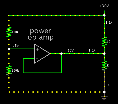
A possible method is a power op amp. It does not waste as much power as a resistive divider would. However it is a resistive drop. It will waste 45 W if you draw 3A from one polarity only.
Its output pin provides a volt level equal to Vsupply/2. It wastes only enough current to maintain this across the load.
And if your positive and negative loads are balanced, the op amp does not need to waste any power at all!
Depending upon the current inbalance between the positive and negative voltages, you may need to heatsink for the power transistors in Borber's circuit. The power dissipated is equal to the current inbalance times 15V.
A circuit as suggested in post #5 and #6 is usually referenced as "virtual ground generator". Without additional constraints it has to supply up to 3A ground current, so the power transistors and heatsinks have to be chosen for 45 W poer dissipation.
Only one common heatsink for 45W is needed because the difference current flows only through one transistor at the tima. Transistors must be isolated from heatsink.
This site uses cookies to help personalise content, tailor your experience and to keep you logged in if you register.
By continuing to use this site, you are consenting to our use of cookies.