Continue to Site

Welcome to EDAboard.com

Welcome to our site! EDAboard.com is an international Electronics Discussion Forum focused on EDA software, circuits, schematics, books, theory, papers, asic, pld, 8051, DSP, Network, RF, Analog Design, PCB, Service Manuals... and a whole lot more! To participate you need to register. Registration is free. Click here to register now.

[SOLVED] 12V to 4V for RF(GSM) power supply. Linear or DC-DC?

Status
Not open for further replies.

Tuppe

Member level 2
Member level 2
Joined
Oct 22, 2011
Messages
46
Helped
2
Reputation
4
Reaction score
2
Trophy points
1,288
Visit site
Activity points
1,789
Hello! I'm designing SIM908 based Car GSM module, in which I need 12V to 4V PSU. The device in 99% in sleep mode in minimal current consumption and GPS only available on-demand.
I've been stuck in this problem for few days, but I don't have the experience to decide surely.

I have 2 choices listed in the datasheet:
1. Linear MIC29302 Regulator
2. DC-DC LM2596
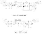
psu.jpg

I already have MIC29302 linear supply with SIM900 and I'm able to get 2,5mA current consumption and the regulator doesn't heat at all. Is DC-DC really necessary? This consumption peaks to unknown range(my multimeter can't pick it up) when RF transmission bursts, so I don't really know what is happening during that period. I'd imagine that full GPS tracker needs DC-DC, but my appliance is mostly sleeping. Do you think full DC-DC worth the hassle, costs and size in my application?

DC-DC is recommended in the datasheet for +12V, but I have no test gear(not even oscilloscope) to measure the noise so it's risky play. How can I reassure that I do not interfere with the RF module?
My options currently:

1. Shielded inductor shield inductor.jpg
2. SMD Ferrite bead
3. EMI cage for PSU. Are these available in general purpose uses? I can't find any.
4. 4 Layer PCB with GND planes top and bottom.

Are these all measures mandatory for proper resoults? Could I get away with 1 and 2?
I plan to mount antennas directly to the module, if that makes any difference.

Thank you very much for reading!
 

Could I get away with 1 and 2?
I plan to mount antennas directly to the module, if that makes any difference.
Basically yes and yes. LM2596 is a relative slow switching device and not expected to generate much high MHz interferences. There should be a ceramic filter capacitor on the right side of the ferrite bead. You also may want to add a ferrite bead on the input side and/or common mode filtering torid cores to stop interferences from being conducted and radiated by the supply cable.

The nearby antenna can pick up interferences radiated from the switch mode regulator. A continuous copper pour on the bottom side below the switching regulator circuit should usually reduce interfernces to an acceptable amount, but only a final try with local versus cable connected remote antenna can tell if you succeded.

A point to consider, even if the ferite bead is rated for e.g. 3A, the inductance may drop to a small fraction due to saturation.

Attenuation at 900/1800 MHz will be probably not affected that much.
 

There should be a ceramic filter capacitor on the right side of the ferrite bead. You also may want to add a ferrite bead on the input side and/or common mode filtering torid cores to stop interferences from being conducted and radiated by the supply cable.
By the filter capacitor, are you referring to the schematic image? Meaning that inbetween FB101 and VBAT, I should add yet another filter capacitor in addition to 330uF and 100nF? Can I use e.g. value of 100nF?
Should I use same type of ferrite bead to input side? I'd like to keep the component differentation to minimum, as I only produce small quantity of units.
For example:
https://www.digikey.ca/product-detail/en/74279224271/732-3427-6-ND/2794569

The nearby antenna can pick up interferences radiated from the switch mode regulator. A continuous copper pour on the bottom side below the switching regulator circuit should usually reduce interfernces to an acceptable amount, but only a final try with local versus cable connected remote antenna can tell if you succeded.
By mounting directly to module I meant that I mount extension cables directly to the module, instead of having external PCB antenna interface. The antenna itself will be placed outside the module(plastic casing).
SIM908 requires bottom GND layer. If I use the same GND bottom layer to module and PSU, would this create interference? As you see, I've not yet grasped the RF analog circuit physics, but I can only make far-fetched guesses.

A point to consider, even if the ferite bead is rated for e.g. 3A, the inductance may drop to a small fraction due to saturation.
What kind of affect would this have?
SIM908 datasheet requires "rated current > 2A, low DC resistance" and 270 Ohm value is in the schematic. Is this 270 Ohm value specific? If I can found anything between e.g. 200-300Ohm version for cheaper, would it defeat the purpose?

Thanks for the info! I feel a bit more confident now. So you'd ditch the linear regulator idea right away?
 

Generally, comtinuous ground plane is preferred. In sensitive analog circuits, I'm sometimes using local power ground for switched mode converters, with single point connection to the commeon ground and effective input and output filtering, to keep injected switching currents from spreading over the common ground plane. But the common ground plane should be continued as well, so the technique can only work in multilayer PCB.

So I think, the common bottom ground solution is best for your design.

A customer of mine has a GSM communication device which is often operated with a SMA plug-on antenna, and it has a LM2596 switching regulator too.

The ferrite bead looks O.K., unfortunately Wuerth gives no DC current dependent impedance curves (neither Murata does). I'm complaining continuously about the point, yet without luck. You can review the Fair-Rite catalog how a useful specification might look like.

I would probably chose a ferrite bead with better GHz suppresion, like 742 792 241 81. The exact impedance value isn't particularly critical.
 
  • Like
Reactions: Tuppe

    Tuppe

    Points: 2
    Helpful Answer Positive Rating
Hello!

I just upgraded my prototype to LM2596 power supply (lc technology sim900 module)

Now it's drawing 25mA! How is this possible? I got 10 times the power consumption with SMPS!

SIM900 is described to have 22mA power consumption in idle mode. I somehow had 2.5-5mA consumption with linear regulator.
**broken link removed**

Is this because the ESR of the cheap capacitors? Why is SMPS taking 10 times more current than the linear MIC29302 regulator?
 

The problem of power supply for GSM is a large pulse consumption during transmission and low current at IDLE.
Here is my source for SIM900
PS.png
 
  • Like
Reactions: Tuppe

    Tuppe

    Points: 2
    Helpful Answer Positive Rating
Interesting, the LM2596 design was from the SIM900 datasheet. What kind of power consumption are you able to get with that circuit? That seems pretty expensive though...

Any idea why did my linear regulator perform better, or must it have been some kind of measurement error? 5mA I had with the linear regulator would be great for me.

Thanks!
 
Last edited:

The problem you are experiencing is minimum current consumption of LM2596 without load, which is considerable higher than with linear regulator. Other switched mode converters are much better in this regard, e.g. the suggested TPS54240.
 
For that low current level I see no reason not to use the linear regulator.
It's simpler and you don't have to worry about switching noise.
 
  • Like
Reactions: Tuppe

    Tuppe

    Points: 2
    Helpful Answer Positive Rating
For that low current level I see no reason not to use the linear regulator.
It's simpler and you don't have to worry about switching noise.
Of course the GSM module will be transmitting occasionally...
 

For that low current level I see no reason not to use the linear regulator.
It's simpler and you don't have to worry about switching noise.
That's why I asked the original question.

I guess I should go back to the linear regulator design? TPS54240 seems interesting, but complicated and expensive for this application, especially if the linear regulator is sufficient.

Thanks FvM for the tip, I didn't think that at all. I still thought it was the capacitor ESR. I just went blindly with the datasheet. I did PCB design and everything with that LM2596, I'm glad that I got this sorted.

Thanks everyone, great info again!
 

Hello! I'm designing SIM908 based Car GSM module, in which I need 12V to 4V PSU. The device in 99% in sleep mode in minimal current consumption and GPS only available on-demand.
!

The easy answer is do a heat loss comparison.
For Buck Regulators, the lower the output, the higher the losses. while LDO's are very sensitive to heat loss with large voltage drops.

BUcks are much cooler at max rated current and LDO's are very cool if very low current is used.

THe power loss if at 1A from 12V to 4V at 75% efficiency or 25% loss of 12W is 3 watts for this Buck regulator while the LDO is 8 watts which is close to the limit, while this Buck can drive 3A max if kept cool.

At 200mA ther LDO drops 8Vx0.2A = 1.6 watt heat loss while the Buck reg from 12 to 4V ( assuming 25% loss again) PL= 0.2A*12V*25% =0.6 watt assuming optimal design choices, otherwise , this is getting close the break even point at < 7% of rated current.

So by all means stick with an LDO for low current otherwise, bulk up on heatsinks > 5W and compute the Rja including case and heatsink for temp rise.

If the duty cycle of the GSM is too long, there will be thermal issues within a few seconds, so a Buck regulator is required and it must be carefully chosen to optimize efficiency perhaps with a standby LDO in parallel for Receive mode to conserve battery power.
 
  • Like
Reactions: Tuppe

    Tuppe

    Points: 2
    Helpful Answer Positive Rating
I believe that in most mobile applications, total energy bilance and in addition peak power capability of the battery are the important parameters. With 12 V battery, a LDO can be acceptable if the GSM module is most of the time in sleep mode (2 mA curent range). If it's receiving in idle mode (20 mA range) for a considerable amount of time, a switched mode converter (with better performance than LM2598) already pays.
It was actually also in "idle mode" with the 5mA consumption(sorry, I messed up the words). In this application the GSM modem must be connected to the network at all times, but everything else is sleeping.

I'm still dubious of that measurement of mine before. It was connected to network with about 5mA current @ 3.8V.
What I've read online some are able to get that kind of consumption too.
But the datasheet says the idle consumption is 22mA, which is crazy high.
I need to be way lower than that, even all of the mobile phones are in the 5mA range, while having the same effect.

I'm pretty much lost again. I need to be in the 5-10mA range, although the SIM900 datasheet says that the idle current is 22mA...
Any advice? Do I need to change the chipset to ublox SARA-G3?

The easy answer is do a heat loss comparison.
That's a good point. It's definitely using mostly less than 30mA, so I think LDO is indeed sufficient.
I'd need to try that configuration again. I'm burning money like no tomorrow with this trial-and-error testing.
 
Last edited:

I'm not working with SIM900, but according to hardware design manual, the modem will connected to network in sleep mode, with only 1.0 to 1.5 mA current consumption. So there might be a specification misunderstanding. Of course I don't know if the manual is correct in all details.
 
  • Like
Reactions: Tuppe

    Tuppe

    Points: 2
    Helpful Answer Positive Rating
I'm not working with SIM900, but according to hardware design manual, the modem will connected to network in sleep mode, with only 1.0 to 1.5 mA current consumption. So there might be a specification misunderstanding. Of course I don't know if the manual is correct in all details.
Oh right indeed! It's indeed in the sleep mode, I have CSCLK=2. I can't believe my absence of mind anymore. I'm glad that I don't need to switch the module because of this.
Thanks again, I need to take a break and see the datasheets and check out those power calculations. I think I can sort this out now with all the information you gave.

Make sure you have the Current surge capacity and power dissipation capacity for Tx which may be 1A .
It's actually 2A for 577us. Datasheet's example power supply circuit has 330uF output cap and 100uF input cap.
I calculated that 2A for 577us takes 4,4mJ of energy at 3.8V.

I get:
330uF@3.8V (2.4mJ) + 100uF@12V(7.2mJ) = 9.6mJ. It seems to be adequate with these calculations, but I'm just starting my first year in EE studies so this is just merely a guess.

Thanks guys! Great support again in the Edaboard!
 
Last edited:

Status
Not open for further replies.

Similar threads

Part and Inventory Search

Welcome to EDABoard.com

Sponsor

Back
Top