Continue to Site

Welcome to EDAboard.com

Welcome to our site! EDAboard.com is an international Electronics Discussion Forum focused on EDA software, circuits, schematics, books, theory, papers, asic, pld, 8051, DSP, Network, RF, Analog Design, PCB, Service Manuals... and a whole lot more! To participate you need to register. Registration is free. Click here to register now.

12V light dimmer circult

Status
Not open for further replies.

loosu

Newbie level 2
Joined
May 2, 2011
Messages
2
Helped
0
Reputation
0
Reaction score
0
Trophy points
1,281
Activity points
1,297
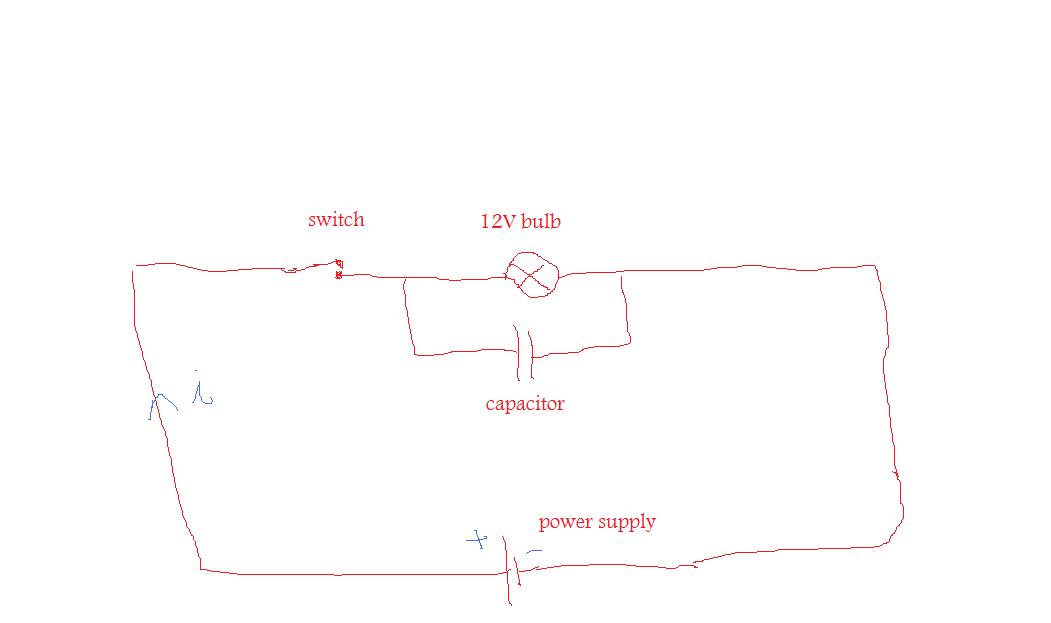
i just want to make a simple circuit . the purpose of this circuit is a 12V bulb is working from 12V DC power supply .
when we switch off the power to the bulb then it needs to fade gradually and comes to a "complete off " rather than a sudden "on" (100% brightness ) to "off" (0% brightness) in a moment . i don't need time delay (i don't need 100% brightness for some period of time once we switch off the power supply , it can start to fade immediately once we switch of the power supply )

here i attached a simple diagram .
please tell me weather it is correct or not ?
if the diagram is correct what capacitor vulvae is suitable for this operation ?
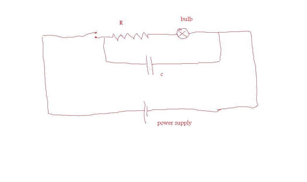
if the diagram is wrong what improvement i need to do ?
the bulb here we using is 12V 10W
desired fading time 3s

please help me . .


Is it your learning purpose only ?
Or else ?
if you want any other circuits for it ?
 

Using only capacitor to fade a 10W light won’t work ..
In theory you need a resistor (in-series) and capacitor (in-parallel) ..
In practice the values will be unreasonable and you’ll be wasting power in resistor ..

In today’s world you can nicely design a small circuit based on a really small microcontroller that will use the PWM (pulse-width-modulation) form 0% to 100% to turn the light on and 100% to 0% to turn it off ..
The “slope” is the matter of a program, will not depend on the value of components, so it can be changed/adjusted at will ..
Google for PICAXE-08 and PWM ..

IanP
:wink:
 

Using only capacitor to fade a 10W light won’t work ..
In theory you need a resistor (in-series) and capacitor (in-parallel) ..
In practice the values will be unreasonable and you’ll be wasting power in resistor ..

In today’s world you can nicely design a small circuit based on a really small microcontroller that will use the PWM (pulse-width-modulation) form 0% to 100% to turn the light on and 100% to 0% to turn it off ..
The “slope” is the matter of a program, will not depend on the value of components, so it can be changed/adjusted at will ..
Google for PICAXE-08 and PWM ..

thanks . . can you please tell me how we need to connect resistor and capacitor ?
what are the values of them ?
please let me know the new diagram is correct i attached here ?
thanks in advance . . .


---------- Post added at 13:29 ---------- Previous post was at 13:17 ----------

can we use 4W bulb instead if 10W
 

Your original circuit will work in principle. It will need a large capacitor.

You asked what if you switch to a 4W bulb. It would draw 1/3 A. Resistance 36 ohms when lit. (Note: Resistance will go down as applied voltage goes down.)

You want 3 seconds discharge time.

Discharge time is typically regarded as 5 RC time constants. A time constant of .6 second will do this.

Time constant formula is R x C.

Solving for C. You need a capacitance of .015 F. This is 15,000 uF.
Originally you asked about a 10W bulb. Then you'll need 47,000 uF (using the same formula).

You really need to use 3 or 4 times these values. This is because the filament will glow only above a certain voltage. And the voltage will drop very quickly after you switch off power.

You can use several capacitors in parallel, adding values together.

However you should not use capacitors in series to store DC. In other words, it will not work to take three 1 F capacitors rated for 5V each, and string them to achieve 15V rating. You'll find they will not charge and discharge equally. You won't get maximum performance. One or all capacitors will get destroyed, unless you take precautions.

Your circuit in post #4 is not recommended. You'll get reduced brightness from the bulb all the time it's on. And you'll need a bulky resistor rated to survive the amount of watts you'll be wasting.
 
I agree on BradtheRad comment and would suggest you use a simple PWM or even using a simple power transistor whit an RC constant has you will be able to use smaller component for the result you are looking for. Cheer!
 

Status
Not open for further replies.

Similar threads

Part and Inventory Search

Welcome to EDABoard.com

Sponsor

Back
Top