Continue to Site

Welcome to EDAboard.com

Welcome to our site! EDAboard.com is an international Electronics Discussion Forum focused on EDA software, circuits, schematics, books, theory, papers, asic, pld, 8051, DSP, Network, RF, Analog Design, PCB, Service Manuals... and a whole lot more! To participate you need to register. Registration is free. Click here to register now.

128x64zw lcd interfacing with fpga

Status
Not open for further replies.

zacief

Newbie level 5
Joined
Jul 18, 2016
Messages
9
Helped
0
Reputation
0
Reaction score
0
Trophy points
1
Activity points
59
hi ,
i have written a code (copied from internet) for lcd and run it on spartan-3cx250E .the problemis that some characters are missing on lcd.
there may be a issue with clock frequecy or enable signal.i dont know how to resolve this?
Thanks 0-02-05-6b0305ba36dfc9d2bc108b01e24b707fad4187c5f7a3f71f9857d1244d0dde1a_full.jpg
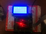

the code is as follows:]
Code:
module lcd12864(LCD_N,LCD_P,LCD_RST,PSB,clk, rs, rw, en,dat);
output reg  LCD_N;
output reg LCD_P;
output reg LCD_RST;
output reg PSB;
input clk;  
 output [7:0] dat; 
 output reg rs,rw,en; 
 //tri en; 
 reg e; 
 reg [7:0] dat; 
  
 reg  [31:0] counter=0; 
 reg [6:0] current=0,next=0; 
 reg clkr; 
 reg [31:0] cnt=0; 
 parameter  set0=6'h0; 
 parameter  set1=6'h1; 
 parameter  set2=6'h2; 
 parameter  set3=6'h3; 
 parameter  set4=6'h4; 
 parameter  set5=6'h5;
 parameter  set6=6'h6;  

 parameter  dat0=6'h7; 
 parameter  dat1=6'h8; 
 parameter  dat2=6'h9; 
 parameter  dat3=6'hA; 
 parameter  dat4=6'hB; 
 parameter  dat5=6'hC;
 parameter  dat6=6'hD; 
 parameter  dat7=6'hE; 
 parameter  dat8=6'hF; 
 parameter  dat9=6'h10;

 parameter  dat10=6'h12; 
 parameter  dat11=6'h13; 
 parameter  dat12=6'h14; 
 parameter  dat13=6'h15; 
 parameter  dat14=6'h16; 
 parameter  dat15=6'h17;
 parameter  dat16=6'h18; 
 parameter  dat17=6'h19; 
 parameter  dat18=6'h1A; 
 parameter  dat19=6'h1B; 
 parameter  dat20=6'h1C;
 parameter  dat21=6'h1D; 
 parameter  dat22=6'h1E; 
 parameter  dat23=6'h1F; 
 parameter  dat24=6'h20; 
 parameter  dat25=6'h21; 
 parameter  dat26=6'h22; 
 parameter  dat27=6'h23; 
 parameter  dat28=6'h24; 
 parameter  dat29=6'h25; 
 parameter  dat30=6'h26; 
 parameter  dat31=6'h27; 
 parameter  dat32=6'h28; 
 parameter  dat33=6'h29; 
 parameter  dat34=6'h2A; 
 parameter  dat35=6'h2B;
 parameter  dat36=6'h2C; 
 parameter  dat37=6'h2E; 
 parameter  dat38=6'h2F; 
 parameter  dat39=6'h30;
 parameter  dat40=6'h31; 
 parameter  dat41=6'h32; 
 parameter  dat42=6'h33; 
 parameter  dat43=6'h34; 
   
  
 parameter  nul=6'h35; 
always @(posedge clk)         //da de shi zhong pinlv 
 begin 
  counter<=counter+1; 
  if(counter==32'h1FFFE)  begin
  counter<=0;
  end
  else if((counter==32'hF)) begin//||(counter==32'h57FE)
  clkr<=~clkr; 
 
  end
en<=clkr|e;    
rw<=0; 

LCD_N<=1'b0;
LCD_P<=1'b1;
LCD_RST<=1'b1;
PSB<=1'b1;
end 
always @(posedge clk) 
begin 

 if(counter==32'hF)begin //counter==32'haff0
		 current<=next; 
		 case(current) 
			 set0:   begin  rs<=0; dat<=8'h30; next<=set1; end 
			 set1:   begin  rs<=0; dat<=8'h0c; next<=set2; end 
			 set2:   begin  rs<=0; dat<=8'h1; next<=set3; end// 
			 set3:   begin  rs<=0; dat<=8'h6; next<=dat0; end 
			// set4: begin rs<=0; dat<=8'h81; next<=dat0; end // 
			 dat0:   begin  rs<=1; dat<="s"; next<=dat1; end //?????
			 //set5: begin rs<=0; dat<=8'h91; next<=dat1; end // 
			 dat1:   begin  rs<=1; dat<="a"; next<=dat2; end 
			// set6: begin rs<=0; dat<=8'h89; next<=dat2; end // 
			 dat2:   begin  rs<=1; dat<="j"; next<=dat3; end 
		// set4: begin rs<=0; dat<=8'h90; next<=dat14; end // 
			 dat3:   begin  rs<=1; dat<="e";next<=dat4; end 
			// set4: begin rs<=0; dat<=8'h90; next<=dat14; end // 
			 dat4:   begin  rs<=1; dat<="s"; next<=dat5; end
//set4: begin rs<=0; dat<=8'h90; next<=dat14; end // 			 
			 dat5:   begin  rs<=1; dat<="h"; next<=dat6; end 
			// set4: begin rs<=0; dat<=8'h90; next<=dat14; end // 
			 dat6:   begin  rs<=1; dat<="a"; next<=dat7; end 
			// set4: begin rs<=0; dat<=8'h90; next<=dat14; end // 
			 dat7:   begin  rs<=1; dat<="r";next<=dat8; end 
			// set4: begin rs<=0; dat<=8'h90; next<=dat14; end // 
			 dat8:   begin  rs<=1; dat<="e"; next<=nul; end 
			
			  nul:   begin rs<=0;  dat<=8'h00;                    // ????E ? ?? 
				         if(cnt!=4'h10)  
                      begin  
                       e<=0;current<=set0;cnt<=cnt+1;  
                      end  
                     else  
                      begin current<=set0; e<=1;cnt<=0; 
                     end  
					   end 	
             

			default:   next<=set0; 
			 endcase 
	end		 
	
end 

endmodule
 
Last edited by a moderator:

Hi,

use a scope and check timing of the interface.
If you need help, then show us the scope picture.
Schematic and a link to the display_datasheet would be good, too.

Klaus
 

yes help will be highly appreciated
 

Attachments

  • Core3S250E-Schematic.pdf
    468.4 KB · Views: 44
  • DVK601-Schematic.pdf
    534.7 KB · Views: 46
  • Digole_12864_LCD.pdf
    1,010.9 KB · Views: 54

Your FSM doesn't make sense, it looks like you tried to combine both parts of a two process FSM (combonational and sequential) into a single sequential always block. That is not correct.

Code:
begin
  current <= next; // this should not exist in a single always process FSM
  case (current)
    set0 : next <= set1; // this should be assigned directly to the current state in a single always process FSM
    ...

You should have tried simulating this with a testbench, you would have seen the incorrect behavior of your FSM before loading it on hardware.
 

Capture.1PNG.PNG

this is the image of scope.enable is not working and i dont know how to resolve the error.can u explain in detail
 

Where is current next and counter? Without internal signals your not goi g to sucessfully debug this.

en is X because you don't set it to anything until state nul. Of course that wont happen when you expect due to your FSM problem I mentioned earlier.

Learn to use a simulator.
 

isim simulate the input signals.you cannot give output signals.we can only give input signals and it use them to evaluate the logic,i haave attached the detailed waveforms.View attachment 138839View attachment 138839

What do you mean, ISIM can display the waveform of any signal (except VHDL variables). There is no restriction of showing an output in the ISIM waveform display, so I have no idea what the issue is with you putting the count, next, and current in the simulation waveform display.

I think you need to go through the ISIM tutorial on Xilinx's website.

- - - Updated - - -

My mistake you do set the value of en at dat3 and dat8 but as it's never initialize it's always going to be X until then. Also didn't notice there was another assignment of en <= clkr | e;. Unfortunately that assignment will always be X as clkr is never anything but X as you have not reset or initial value assigned to the clkr reg.

You need to learn Verilog, not just jump in and start coding with it.
 

heres a new waveform by halfing the values of counters
cnt!==2'h2 replaced by cnt!==2'h1
counter==32'hF replaced by counter==32'h7
counter==32'h1FFFE replaced by counter==32'hFFFFView attachment document1.pdf
 

What is the point of this new post? i've already explaned that en is X because the clkr is X.

Besides you still haven't learned how to display internal signals in your waveform display. You might acually understand the problem if you look at the internal signals.
 

kindly link me some document regarding the simulation of internal signals.i set the initial value of clkr=0 but the problem is same.
 

Status
Not open for further replies.

Part and Inventory Search

Welcome to EDABoard.com

Sponsor

Back
Top