Continue to Site

Welcome to EDAboard.com

Welcome to our site! EDAboard.com is an international Electronics Discussion Forum focused on EDA software, circuits, schematics, books, theory, papers, asic, pld, 8051, DSP, Network, RF, Analog Design, PCB, Service Manuals... and a whole lot more! To participate you need to register. Registration is free. Click here to register now.

[SOLVED] 120v Series Battery Charging?

Status
Not open for further replies.

DC177E

Newbie level 6
Joined
Mar 15, 2012
Messages
11
Helped
0
Reputation
0
Reaction score
0
Trophy points
1,281
Activity points
1,370
Hello,

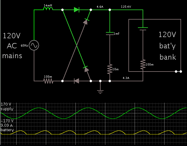
We have an electric car project which has 8-10 12v SLA batteries in series as a power source. In order to charge this, we need a ~120v ~15a DC power supply to feed into a custom board that controls current and such via mosfet. Because of the high power, we were thinking of just taking the output from a 1:1 transformer (for safety) and rectifying it. Unfortunately, we cannot find any appropriately priced (<120$) transformers suitable for 13-15a. If anyone knows where we could find one such transformer, or has a better idea as to a power supply, we would appreciate it.

Thanks,

Dan
 

You may as well try it without a transformer. Of course you should carry out sensible safeguards (such as preventing your system from touching grounded metal objects).

One thing you want to do is limit current going into your batteries. Since you are drawing AC mains power, at several amperes, it is practical to install a coil in series. Its reactance will reduce current.

My simulation shows you'll get sufficient reactance with a value of 14 mH.

The charging current will automatically reduce as the battery charges. When the battery bank is down around 100 V, it will receive current peaks upwards of 20 A. As it charges up to 145 V, current will drop to 2 or 3 A.

Your coil should be wound with wire of a thick enough gauge to handle 15 A average. Say 14 AWG.

This is the result of simulation only. You'll need to do tests, to find out how well it works.


A fuse should be installed where the .1 ohm resistor is.

The smoothing capacitor (labelled 1 mF) may be unnecessary.
 

One thing you want to do is limit current going into your batteries. Since you are drawing AC mains power, at several amperes, it is practical to install a coil.

Wow, that coil idea is rather genius. We do, however, have a 'smart' charger of sorts in the works, to limit charge current and such.

I will, however, definitely skip the transformer - thanks, solved my problem.
 

For personal safety purposes, I would include a GFI in the charging circuit. Those are inexpensive and can be found on most hardware stores.
 

Wow, that coil idea is rather genius. We do, however, have a 'smart' charger of sorts in the works, to limit charge current and such.

I will, however, definitely skip the transformer - thanks, solved my problem.

please tell me what are those component 100m
regards ardavan
 

please tell me what are those component 100m
regards ardavan

I guess you mean my simulation which has the 100 milli-ohm resistors?

I add them to create some amount of resistance in the power supply, or in components which carry heavy current.

Sometimes it is important to factor in such resistance. Sometimes not so important.

Sometimes if there is no resistance, the simulator will display an error message (convergence failed), and stop running. This happened with my schematic, until I added the resistors. Just now I am trying it again, and again it is happening.

Sometimes if there is no resistance, current reaches impossibly high levels. This also happened with my schematic, until I increased the resistance to 1 or 2 ohms.
 

Status
Not open for further replies.

Part and Inventory Search

Welcome to EDABoard.com

Sponsor

Back
Top