Continue to Site

Welcome to EDAboard.com

Welcome to our site! EDAboard.com is an international Electronics Discussion Forum focused on EDA software, circuits, schematics, books, theory, papers, asic, pld, 8051, DSP, Network, RF, Analog Design, PCB, Service Manuals... and a whole lot more! To participate you need to register. Registration is free. Click here to register now.

12 Volts to 3.3 Volts - Help with Chip Selection

Status
Not open for further replies.

campus189

Member level 5
Joined
May 7, 2011
Messages
84
Helped
0
Reputation
0
Reaction score
0
Trophy points
1,286
Location
Tennessee,USA
Activity points
1,940
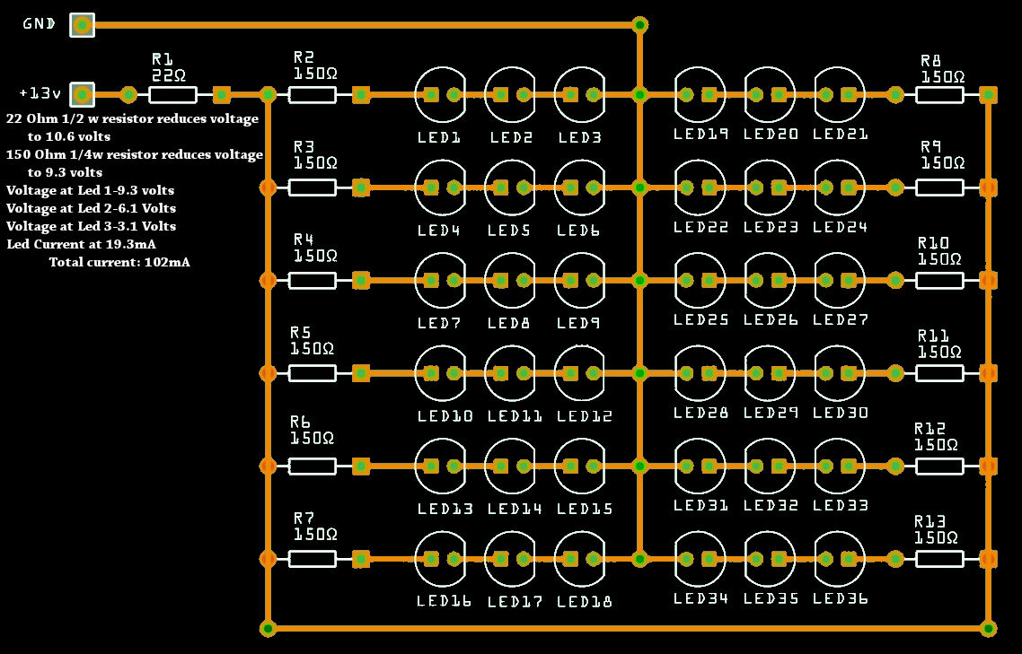
Want to power 24-led's for an emergency lighting project for when the power goes out.
Will be running off a 12 Volt deep cell marine battery that is charged by solar panels.

Led Specs- 3.2-3.4v 20mA each X 24 =480mA total

I am currently using these to go from 12 Volt to 5V.
The reason i'm using them is because I have alot of these & can get more cheap.

**broken link removed**

**broken link removed**

**broken link removed**

**broken link removed**

My output voltage on the adapter I have.....

Pin 1 ----Ground
Pin 2 ----2.1 Volts
Pin 3 ----2.8 Volts
Pin 4 ----5.2 Volts

Heres my question to you..

There are so many chips to choose from, i don't know where to start..

From what I can gather, My best options would be these chips listed below.

All these are TO-220 style

LM2678S-3.3 Max Voltage In- 12V,---5A
LM1117-3.3 Max Voltage In- 15V ---800mA
LM1086-3.3 MAx Voltage In- 5V,----1.5A
LM3940 MAx Voltage In- 5.5V---1.0A

Anyone got an idea which one to go with ?
If I can keep from using lots of resistors & other components, that would be great.

It looks like if I used the LM2678S-3.3 I would have a heatsink with alot of wasted power.
But, I wouldn't have to use the adapter above to go from 12v-3.3

It looks like the LM1117 or LM3940 would be best for this.

With the LM3940, it calls for a minimum output capacitance required to maintain stability. Which is 33 μF
Any recommendations on capacitors ? or should I go with the minimum?

According to datasheet, value may be increased without limit.
Larger values of output capacitance will give improved transient response.
ESR LIMITS:
The ESR of the output capacitor will cause loop instability if it
is too high or too low. The acceptable range of ESR plotted
versus load current is shown in the graph below. It is essential
that the output capacitor meet these requirements, or
oscillations can result.

Or would I be better off modifying the 12v adapters I have?
I have been working on this for a while now, modifying the 12 volt adapter and KJ6EAD has been helping me here.


I'm trying to K.I.S.S. (Keep It Simple Stupid) , lol

Any help would be appreciated..

Thank You
 
Last edited:

For such project it’s very important not to waste too much energy. Start simple by placing the series of 3 LEDs and one 100 ohms resistor for a total of 8 strings…
 
Last edited:

TY, I'll give it a try :)

Would this work? Or should I go with what u said?
led.jpg
 
Last edited:

Yup, that above configuration should work, giving you a current through the LED's of about 17.5mA. I'm impressed that someone took the time to make that LED wizard! Where did you get it from?
 

**broken link removed**


This website is great. Tells all kinds of things about led's
 

Ok,

After a lot of tinkering around with using online resistor calculators, I got a lot of wrong values.
I did a lot of designs on a bread board & finally achieved my goal.
I used Led's that were rated for 3.3 Volts 20mA Max.
My goal was to create an emergency light system that ran from 2-Marine Deep cell batteries that were charged from 2-45w Solar panels.
I wanted these lights to run as long as possible without drawing a ton of amperage from my batteries.
I'm sure a lot of people think I'm crazy for doing this, but when you lose power for 2-3 days at a time it gets old.
Plus I needed something to keep me busy,lol
I'm sure someone can suggest different resistor values, but when using online resistor calculators, I would have led's or a Printed circuit board that would get hot or very warm.
When I experimented with different resistors, I came up with a kick-butt solution.
This design did NOT draw a lot of power and the lights were blinding as anything.
I could run 9 of these at 36 Led's per PCB for a total of 324 Led's and still be under 1A, which is awesome.
Keep in mind, I'm having a hard time remembering all the electronics from High school, which has been a while :(
In other words, I'm a noob.
Hopefully this helps someone out..


I'm sure someone can suggest different resistor values, but when using online resistor calculators, I would have led's or a Printed circuit board that would get hot or very warm.
I don't see why, the power dissipated by the resistors is very small. And for that reason, you can remove R1.

When I experimented with different resistors, I came up with a kick-butt solution.
Instead of experimenting, let's do the math, shall we? First, you pick # of LEDs in series such that even at low battery voltage, you still have some voltage drop over a series resistor. With 4 in series, you'd need 12~13V minimum - that's too much, so you take 3 LEDs in series.

Next, you decide (not calculate!) maximum LED current. Let's say the 20 mA they are specified for.

Then you need to calculate minimum value for series resistor, such that for maximum battery voltage (let's say, 14V), and lowest possible voltage you'll see across the LEDs (with chosen current through it, let's say 3.3V), the resistor limits the current to chosen value. Voltage drop across series resistor then is 14 - (3 * 3.3V) = 4.1V. Required resistor value: 4.1V / 0.02A = 205 Ohm, let's round that up to 220 Ohm.

Now, check what you get with chosen value: maximum current = (14V - 3 * 3.3V) / 220 Ohm = 18.6 mA. Each LED dissipates 3.3V * 18.6 mA = 62 mW. A bit on the high side for a 5 mm LED I think, but if the specs say that's okay, that should be okay... :smile: (perhaps make sure not to pack the LEDs to tightly on the board, so that each LED gets enough air cooling). Resistor dissipates 4.1V * 18.6 mA = (4.1V)^2 / 220 Ohm = 76 mW. Read: no problem, even a 1/8W or SMD resistor can handle that. Each set of 3 series LEDs + resistor then dissipates 14V * 18.6mA = 0.26W. Battery power -> LED power efficiency = (3 * 3.3V) / 14V = 71%, pretty good and this gets even better at lower battery voltage.

Then, build test circuit of a single 3 LEDs + resistor combo, and measure / check / adjust resistor value to taste. Remember the resistor limits the maximum LED current, as the battery voltage drops this current will lower, LEDs will dim slowly & further battery drainage will slow down.

Last: simply multiply # of (3 LED + resistor) groups such that (battery doesn't drain too quickly) and (you can see what you're doing during power blackouts). :lol: Total battery current = single LED current * number of groups. For example with 36 LEDs (12 * 3) and 220 Ohm resistors, you'd draw 12 * 18.6 mA = 0.22A (-> each AmpHour battery capacity = at least 4.5 hours light).
 

Thanks for the reply.
Now you got me thinking :)
I got a feeling theat the led's I got are not the best quality, i could be wrong, but i got a great deal on them from flea-bay,, why I bought them.
I tried the 120 & 150 Ohm resistors, & got heat as I said.
At first I over complicated the issue by having a usb car adapter included in the the design.
Once I used just a PCB, Led's & resistors, it became a lot easier to figure out.
I am re thinking my design after reading your post..
Thanks again.
 

I found simple converter circuit with IC MAX but you must change IC number to MAX604 (3.3 V output) thus circuit as below.
**broken link removed**
 

The 5mm LED's you can test for ESR and you should find them to be around 8~16Ω each @20mA and fairly well matched in the same batch.
I would consider a Ni-MH battery pack from an electric drill. Choose one that matches the optimal load voltage of the PV panel such as a 24V panel running at 18.5V battery pack.. Then choose a string of LED's that leaves <1/2 the LED voltage to limit the current so power loss is minimized.

But if you want to use the 12V battery from 12~13V, a string of 4x3.2V is pretty close. But you need to limit the max voltage of the charger and not use a 14.4 otherwise you need a current limit for the LED strings, which typically drops 1.2V min. I run my 4x1W LEDs off 12.8V rectified and filtered. with 15 strings in parallel. Other convenient arrays use 19.5 or 19V laptop chargers to run strings of 6 in parallel. from 65 or 85W chargers. load caps with low ESR help smoothen the charger... Use a higher power current limiting resistor or use much smaller value for each string. Thermal runaway can occur if you over drive the LED's with no external limiter from a CV source, and 5mm LEDs have no heatsink... But with 1W devices, a good heatsink can regulate the temp vs V diode characteristics so a minimal series R is needed.

Most people need to use CC limiters after a CV source but this is lossy for low V but OK say for 48V with a 2V drop in the current limiter. But I prefer to manage the ESR distribution, and choose stable CV sources that will achieve lower loss so that the current limiter resistance dissipates less than each diode. Since PV source is not stable for voltage, nor is a lead acid battery, you may need to consider my 1st choice for you and that is a 18.5V NiMh source. with PV rewired for 24V OCV.

For example 3V Li cells work great on White LEDs direct without series R when you match the LEDs to the cell voltage. Supplier choice is key.
 
Last edited:

@campus189 < regarding your design in post #6.
20mA x 150 = 3.0V Since these LED's have an ESR of 10~16ohms from my experience (HB type), dropping the current 10% means a drop in voltage of 2mA*13ohm= 26mV, & dropping to 10mA would be ~ 10mA*13mA = 0.13V If you renter into that form calculator 3.3V or say 3.2V, you can gain an extra LED and use a much smaller resistor using 10mA.. you won't notice as much loss in intensity as you will appreciate doubling the power on time (almost) Consider the battery voltage range from 12.5 to 13.5 and recalc. The variation in LEDs in batches is mainly due to ESR so some will get 3.2 others 3.4 etc. In any case the calculator fails to account for the change in voltage due to the internal ESR so it fails to optimize the result for a range in battery voltages. My suggestion is to try a string of 4 LEDs from 12.5 to 13.5V and notice the change in current from 5 to 20mA using 22 ohm series resistors or about 2x the internal ESR. This will eliminate most of the wasted heat in the resistor. But warning if you have a charger that goes to 14.4 V your current will be too much.. ANother solution is to use a 12V halogen bulb which increases in resistance as the current increases. Or goto digikey.com and search for PTC around 20ohms to protect against over current with a high charger voltage. This is an efficient use of power but the compromise is in current variation as the battery gets weaker, so do the LED brightness which is good since you can extend the time.

- - - Updated - - -

Rajat the lm2576adj will work but is only 75% efficient in this application which is like using 3 LEDs in series and wasting power in the 4th part the 150 ohm resistor, which gives you 75% efficiency. With 4 LED's and 22 to 33 ohms you can get 96% efficiency. 20mA*22ohm = 440mV/13V=3.4%

Campus gal<< The isolated 22ohm feed resistor for the array could be replaced by one PTC Use this to choose a suitable Holding CURRENT.
If you ran an array of 3P4S or 3 in parallel with 4 in each series string then choose a holding current of 60mA
if you run 6P4S choose 120mA or less. I would select the string resistor for 15mA max and then 6x15 =90 and choose a holding current of 100 mA for decent margin on max LED current.
these are 100mA 0.32$ ea https://www.digikey.ca/product-detail/en/RXEF010/RXEF010-ND/1045821


but in the end, if you know the ESR of all the LEDs you can choose all the R's to be really small <<<50ohm pref 10 to 20
I use 50 mohm for 100W arrays.
 
Last edited:

Status
Not open for further replies.

Part and Inventory Search

Welcome to EDABoard.com

Sponsor

Back
Top