Alpaslan_Ersoz
Junior Member level 2
Hello,
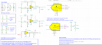
I have an external 12 bit ADC (ADS7886) on a custom designed PCB with SMT32F767. This ADC interfaces with the microprocessor with SPI. Now my problem is that I couldn't read digitized values correctly. Maybe because of the incorrect driving of the ADC or setting of SPI. Based on the ADC datasheet, I should set ADC SCK as 20 MHz, but I couldn't do that with SPI. Because I can set only either 13.5 Mbits/s or 26 Mbits/s baudrate of the SPI. So how can I correctly drive ADC and read the digitized values?
Thank you
This main code:
This is SPI settings:
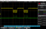
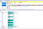
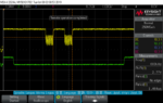
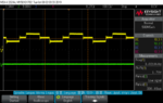
I have attached ADC SCK (Yellow figure), ADC CS and SDO (Green figure), ADC input signal (Biphasic yellow signal), and ADC output (Table results in debugger).
I have an external 12 bit ADC (ADS7886) on a custom designed PCB with SMT32F767. This ADC interfaces with the microprocessor with SPI. Now my problem is that I couldn't read digitized values correctly. Maybe because of the incorrect driving of the ADC or setting of SPI. Based on the ADC datasheet, I should set ADC SCK as 20 MHz, but I couldn't do that with SPI. Because I can set only either 13.5 Mbits/s or 26 Mbits/s baudrate of the SPI. So how can I correctly drive ADC and read the digitized values?
Thank you
This main code:
Code:
void ADC_Conversion_of_Voltage_Transients()
{

		HAL_GPIO_WritePin(ADC_CS_GPIO_Port, ADC_CS_Pin, GPIO_PIN_RESET);
		HAL_SPI_Receive(&hspi4,ADC_Buf,2,100);
		HAL_GPIO_WritePin(ADC_CS_GPIO_Port, ADC_CS_Pin, GPIO_PIN_SET);
		Sample = (((uint16_t) ADC_Buf[1]) << 8 | ADC_Buf[0]);
		//Sample = 0x0 << 12 | ADC_Buf;
		volt = (float)(Sample * (5.0 / 4096.0)); //
		testdata_in[i++]=volt;
		i %= 16;

}
Code:
/* SPI4 init function */
static void MX_SPI4_Init(void)
{

  /* SPI4 parameter configuration*/
  hspi4.Instance = SPI4;
  hspi4.Init.Mode = SPI_MODE_MASTER;
  hspi4.Init.Direction = SPI_DIRECTION_2LINES;
  hspi4.Init.DataSize = SPI_DATASIZE_16BIT;
  hspi4.Init.CLKPolarity = SPI_POLARITY_HIGH;
  hspi4.Init.CLKPhase = SPI_PHASE_2EDGE;
  hspi4.Init.NSS = SPI_NSS_SOFT;
  hspi4.Init.BaudRatePrescaler = SPI_BAUDRATEPRESCALER_4;
  hspi4.Init.FirstBit = SPI_FIRSTBIT_MSB;
  hspi4.Init.TIMode = SPI_TIMODE_DISABLE;
  hspi4.Init.CRCCalculation = SPI_CRCCALCULATION_DISABLE;
  hspi4.Init.CRCPolynomial = 7;
  hspi4.Init.CRCLength = SPI_CRC_LENGTH_DATASIZE;
  hspi4.Init.NSSPMode = SPI_NSS_PULSE_DISABLE;
  if (HAL_SPI_Init(&hspi4) != HAL_OK)
  {
    _Error_Handler(__FILE__, __LINE__);
  }

}
I have attached ADC SCK (Yellow figure), ADC CS and SDO (Green figure), ADC input signal (Biphasic yellow signal), and ADC output (Table results in debugger).
Attachments
Last edited by a moderator: