Continue to Site

Welcome to EDAboard.com

Welcome to our site! EDAboard.com is an international Electronics Discussion Forum focused on EDA software, circuits, schematics, books, theory, papers, asic, pld, 8051, DSP, Network, RF, Analog Design, PCB, Service Manuals... and a whole lot more! To participate you need to register. Registration is free. Click here to register now.

100 KHz MOSFET gate drive with op-amp

Status
Not open for further replies.
I don't think a single opamp can provide enough current for fast switching but you don't provide any info about the implementation either.
 

That was interesting dialog

dexter0904 said:
a suggestion for 100 KHz MOSFET gate drive with op-amp
alexan_e said:
an opamp can't provide enough current
dexter0904 said:
Well That is obvious...

Maybe if you actually take some time to explain properly what you are asking we would be able to help
 

No actually I would like a description of what he is asking, first hint was 100 KHz MOSFET gate drive with op-amp and now he has added "I have to use 2 MOSFETs in half bridge with inductive load at 20Amps"

There is no description of the control device , the purpose of the mentioned opamp , the voltages involved ...
 
Hi,
As already mentioned above, you need to provide details on your control scheme and what you're trying to achieve and specifically with what you need help / suggestions.

If it is concerning gate drive, you should look into half-bridge MOSFET drivers (high/low side). Since you have a half-bridge configuration, one of the MOSFETs is in high-side configuration while the other is configured as a low-side switch. There are other methods of drive, but I prefer using dedicated driver chips.

I have assumed that you require suggestions regarding MOSFET drive. However, only when you provide a detailed explanation of your control scheme and where help is required can an appropriate response be provided.

Hope this helps.
Tahmid.
 
Perhaps, I might not able to express my query correctly....

I have Mosfet Drive ICs like PC923 and TLQ250.... They don't work at 100KHz...

Their are other gate Drivers from LTC, Texas Inst. and Microchip(I had my research),
but their is availability issue and Learning Enthusiasm to build my own with "always-having" components like op-amps and transistors etc....

I'm not an Analog guy but had basics at university level, and not shy of technical details....

For testing i have a Brushed-dc motor 24V rating... and a universal (Series dc) Motor.
The ultimate Goal is to make an inverter....but first things first, hence the Query....

best Regards,
Waqas.
 

Getting an op amp to work will be much more difficult than finding a proper gate drive IC, I guarantee it. Op amps generally do not tolerate capacitive loads well.

IXYS, IRF, and STM all make good high speed drivers, and 100KHz should be easily attainable.
 
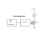
mosfet.pngtest arrangement.pngWell, those comments are pretty help full...
There are some op-amps that are capable of driving un-limted capacitive load
**broken link removed**

I thought it is possible because I have seen some circuits on some websites for MOSFET Gate Grive, but they are limited to about 20kHz...like (9. MOSFET Drive 1.)
https://www.picotech.com/applications/pwm_drivers/#chap1
I guess it would give better results at higher frequencies if we somehow add a rail-to-rail output cum capacitive load drive Op-Amp...
I'll use Drive ICs if have no other option left :p

Best Regards,
Waqas
 

There are some op-amps that are capable of driving un-limted capacitive load
**broken link removed**
Correct, there op some amps which can tolerate heavy capacitive loads. For effective gate driving, you also need high output current and slew rate. For example the lm8272 in that article has a max output current of 65mA, which is very low for gate drive applications. Simple and inexpensive gate drive ICs have peak current ratings of several amps.

When you think of it, there's no reason to expect an op amp to inherently perform better than a gate drive IC. Both will have either a totem pole or push pull output stage inside them which defines the current handling capabilities. A gate drive IC is a much simpler device because it simply switches its output between two stages. It doesn't use feedback like an op amp, so there are no issues with bandwidth and stability. But gate drive ICs are specifically engineered to perform reliably for this application, while op amps are not. If you simply want two switch a gate voltage between two levels, then there's no reason to use an op amp. If for some reason you need more elaborate control of the gate voltage, then maybe an op amp would have some advantage.

I thought it is possible because I have seen some circuits on some websites for MOSFET Gate Grive, but they are limited to about 20kHz...like (9. MOSFET Drive 1.)
https://www.picotech.com/applications/pwm_drivers/#chap1[/quote]Maybe that specific circuit is limited to 20KHz, but gate drivers in general are not. I've used some gate drive ICs in excess 200KHz at high power (like 500W), and 2.5MHz at lower power levels (around 50W).

If you can't find a supplier for specialized gate drive ICs, then building a discrete one is perfectly feasible. The one in figure 9 of that document gives the general idea, it's a big logic inverter. But by carefully selecting components and adjusting the design, you can make them work at 100KHz or more. If you want help designing a discrete driver, then I'll be glad to help. But I'm going to insist the op amp idea isn't going to work, or at the very least it would require extremely specialized components, and it still wouldn't work better than a logic gate driver.
 

If for some reason you need more elaborate control of the gate voltage, then maybe an op amp would have some advantage.

Even then you'd probably want some sort of a current-amplifying voltage buffer stage to drive the MOSFET from the op amp output, especially at higher frequencies.
 

If for some reason you need more elaborate control of the gate voltage, then maybe an op amp would have some advantage.
Nop, Its just switching...

Maybe that specific circuit is limited to 20KHz, but gate drivers in general are not. I've used some gate drive ICs in excess 200KHz at high power (like 500W), and 2.5MHz at lower power levels (around 50W).
great
But I'm going to insist the op amp idea isn't going to work, or at the very least it would require extremely specialized components, and it still wouldn't work better than a logic gate driver.
ok, Blast Op-Amp
If you want help designing a discrete driver, then I'll be glad to help.

Great, So Lets Start with Simplest things that are confusing at the first place...
1. Zenner Selection for Gate...?
I have seen a post by " FvM " that most MOSFETs even Power MOSFETs has a V(GS) limit of 20 Volts Max(though they are more tolerant to ESD)... So, I think 15Volts Zener at Gate is Just fine in save limit...right ?
2. I have seen on many websites that recommend N-channel MOSFET(or NPN-BJT ) as a Low Side Switch and p-Channel(or PNP-BJT ) as high side switch...
even in Half Bridge/Full Bridge Configuration.....

This is confusing because I have seen opposite at many other place in half/full bridge and push pull stage,
and
all NPNs(or N-Channel MOSFETs) in half/Full bridge
or
NPN(or N-Channel FET) as high side Switch and PNP(or P-Channel) as low side switch....

is there any rule of thumb or any further reading you recommend..?

Regards,
Waqas
 

N-channel MOSFETs in high-side configuration require high-side switching. This is slightly complex when compared to driving P-channel MOSFETs by just pulling the gate low or a to low enough safe voltage level. When the drain of an N-channel MOSFET (high-side) is at, for example, +12V, to completely drive the N-channel MOSFET will require a minimum of 8V (VGS) + 12V (since source will be at 12V) = 20V. This is greater than the supply voltage and will thus require a bootstrap driver, charge pump or other method to realize the required higher voltage.

NPN transistors are used as high-side switches with PNP transistors as low-side when a buffering action is required from a single input (common base to both transistors). When the input is high, the NPN transistor will act as a voltage follower (bear in mind the voltage drop, usually 0.6V or 0.7V). When the input is low, the PNP transistor will sink current and the output will be zero.

When high power is required, usually all 4 MOSFETs are N-channel MOSFETs. This is because, P-channel MOSFETs tend to have higher RDS(on) compared to similarly rated N-channel MOSFETs, thus contributing to higher losses. Also, if you use a dedicated driver, driving an N-channel MOSFET at high voltage and high frequency is actually an easier task compared to driving the P-channel MOSFET at high voltage and high frequency provided you can find a suitable P-channel MOSFET with a high enough voltage rating.

Hope this helps.
Tahmid.
 
Status
Not open for further replies.

Similar threads

Part and Inventory Search

Welcome to EDABoard.com

Sponsor

Back
Top