Continue to Site

Welcome to EDAboard.com

Welcome to our site! EDAboard.com is an international Electronics Discussion Forum focused on EDA software, circuits, schematics, books, theory, papers, asic, pld, 8051, DSP, Network, RF, Analog Design, PCB, Service Manuals... and a whole lot more! To participate you need to register. Registration is free. Click here to register now.

0-10V output depending on inputs

Status
Not open for further replies.

paulked

Newbie level 3
Joined
Dec 21, 2011
Messages
4
Helped
0
Reputation
0
Reaction score
0
Trophy points
1,281
Activity points
1,313
Hi there.

I would like to solve a problem electronically rather than using relays (as I am doing at present).

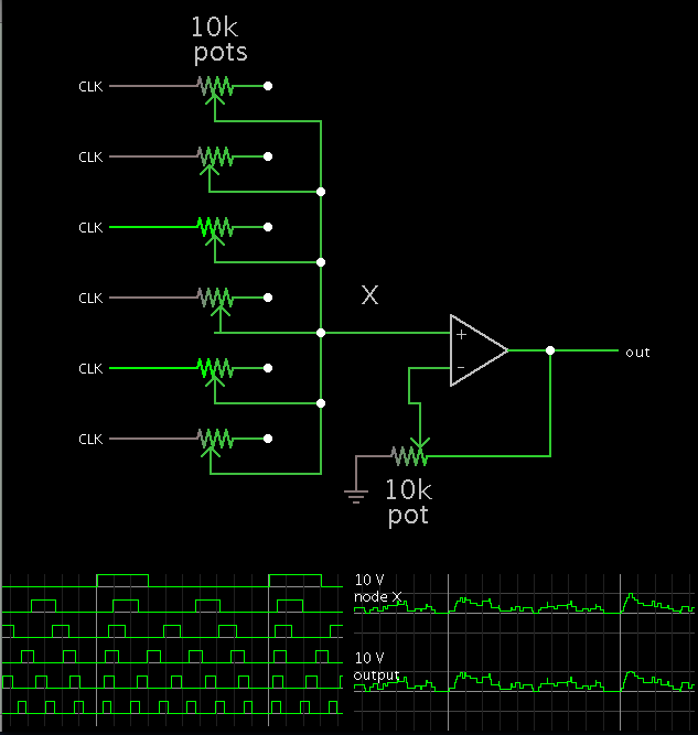
I have to control the speed of a pump (via 0-10V signal) depending on the demand from various sources. I have 6 sources and some require more pump output than others. If more than one source is demanding then those demands are added. The circuit I'm using at the moment is this:

Basic relay control.png

X1-1 - X1-6 Demand inputs
X1-8 = 10V
X1-9 = Output
X1-10 = 0V

This works ok for fixed demands but every time any of the demands change I have to change the value of the resistors.

Any ideas how I should approach this electronically?

Best regards

Paul Ked
 

If the amount of the 6 demands change, you currently have to change resistors. But in the new system you are still going to have to change something. What are you willing to consider as not being too much of a bother?

You could design a custom digital to analog converter, where each of the 6 digital inputs enables a separate current source. But those 6 current sources, while not involving relays, will still have a resistor or something like that to change. You did not say how someone comes to know that the demand has changed from a given source. If it is automatic through realtime instrumentation, you could consider using that instrumentation to control the pump speed directly.

Rather that using feedforward control (as you are doing now) you might consider feedback control. That is where you sense that the pump is falling behind the demand and raise the control voltage according to that measure of how it is falling behind. The disadvantage of feedback control is that the corrective action is delayed until you can sense the deficiency. With feedforward control, you apply corrective action immediately upon knowing that demand has increased. That may or may not be a problem. If the time it takes to increase pump activity is small enough, the pump will speed up before the deficiency becomes too bad. I am speaking in general terms about deficiency because I don't know what your pump does. If, for example, the pump filled a reservoir, the deficiency would be the level in the reservoir. If the pump has to maintain a given pressure with some sort of accumulator, the deficiency would be the amount that the pressure has fallen.
 

Thank you for quick response.

The pump is feeding hot water to heat exchangers in 6 different areas of a building. Each of these areas is thermostatically controlled. The layout of the building is changed about twice a year and this is when we need to change the ratios of hot water to the heat exchangers.

I was thinking of using potentiometers but don't have a clue what to feed them into to prevent a short circuit!

- - - Updated - - -

Would this kind of thing work?

Poss add control.png
 

Short of the solution of installing temperature sensors in the vents of the heat exchangers...

Suppose you were to monitor the water temperature returning from the loops? By way of six inexpensive sensors, mounted on each return pipe. (Each sensor must be located a sufficient distance from the junction block.)

You would still need to account for the length of return pipe to each heat exchanger. A long pipe will give the water more chance to cool until you can measure it. Hence you will need to compare return pipe temps with direct measurement of temp at their respective heat exchangers.

This idea can work only if there is continuous circulation through all pipes. If any pipe gets turned off, then you can no longer detect what is going on at that particular heat exchanger.
 

The system is piped like this:

Layout.png

The pipeline going out from the boiler house is underground and is T'd into for each heat exchanger and each one has a flow control valve on (not shown). The valve shown is opened by a thermostat and I get a signal to say that the valve is open. As is, the system works perfectly well with the relay setup I have done but when they make changes to the flow control valves I will have to change the resistors to alter the pump speeds again.

If I can make up a board with pots on it will make setting up in future much easier, this is what I am struggling with.
 

Starting with your post #3 schematic, I revised it to make a simulation of a 6-channel summing op amp.

Each channel has its own potentiometer, so that you can adjust weighting percentages.

The output ranges from zero to 10V, to vary speed of the motor.

It is important that your 6 control lines provide a high-low input, that is, a path to ground as well as a path to supply +.
If they do not provide a path to ground, then I believe you can make it work by attaching a ground connection to the free end of the pots.

 
Thank you for that, I'll have a play around with it.

Best regards (and Seasonal Greetings!)

Paul Ked
 

Status
Not open for further replies.

Similar threads

Part and Inventory Search

Welcome to EDABoard.com

Sponsor

Back
Top