Continue to Site

Welcome to EDAboard.com

Welcome to our site! EDAboard.com is an international Electronics Discussion Forum focused on EDA software, circuits, schematics, books, theory, papers, asic, pld, 8051, DSP, Network, RF, Analog Design, PCB, Service Manuals... and a whole lot more! To participate you need to register. Registration is free. Click here to register now.

Battery voltage warning

Status
Not open for further replies.

JordanElektronika

Junior Member level 2
Joined
Jun 25, 2015
Messages
22
Helped
0
Reputation
0
Reaction score
0
Trophy points
1
Activity points
311
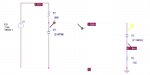
Good day! I have 2 circuits. The idea is to show a warning when the battery drops under 3.3V from 4.5V. Do you think they will work. One of them will turn off the diode when the voltage drops, the otherone will start the diode when the voltage drops. I am worried will the diode burn, because its connected directly to ground or because the current or voltage is too high.

On this schematic the diode turns off, when the current is too low to power it. The idea is when the current is 6mA the diode is active a little and almost impossible to see.
Testing-programs.jpg

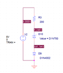
On this schematic when the zener can not hold 3.3V, the LED after it does not get activated. The current can not pass through the diode before the Voltage is 3.3V.
Testing-programs-v2.jpg
 

Attachments

  • Testing-programs.jpg
    Testing-programs.jpg
    77.2 KB · Views: 83
  • Testing-programs-v2.png
    Testing-programs-v2.png
    8.3 KB · Views: 89

Hi,

I'd say with both circuits the diode shuts OFF when voltage drops.

And with both circuits I'd say the problem is that they drain out battery.

Klaus
 

Hi,

I'd say with both circuits the diode shuts OFF when voltage drops.

And with both circuits I'd say the problem is that they drain out battery.

Klaus

How the does the diode shut off through the zener on the second schematic, which requires 3.3V for the zener to break through and allow any current to pass?
 

Hi,

It seems the schematic is from a simulation tool.
Did you simulate various input voltages to see how diode current behaves?

Btw: a LED with 6mA is still very good visible. I'd say without direct comparison to a 20mA driven LED you won't recognize the difference.

Klaus
 

I dont have simulation libraries for OrCAD in order to simulate it, I can only draw it. I am trying to find an online circuit simulator now, if you can suggest something (a portable software would be the best) I will download it.
 

Hi,

A free simulation tool is LTspice.
This surely will work for your circuit.

There are other simulators, but I don't have the experience to say which one is better.

Klaus
 
Last edited:

Ok. I will download it and test it. In 15 to 30 min I will post the result.

- - - Updated - - -

It seems to work. But its giving me a voltage drop over the LED of 0.8V. Also it does not has enough models. There is no 3.3V zener, the LEDs start from 5V plus one with no description at 0.8V.
 

Hi,

What about replacing the Zener with a PNP (base) and biasing the base so it turns on around 3.3V? ...then the LED (from the PNP collector to ground) can have it's own current limiting resistor and be fully off for a good part of the time, until needed, and presumably a less battery wasteful design, if a comparator is not appropriate.

I'm surprised there is no 3.3V Zener, but still. In LTSpice is there the option of modifying the part (LED) parameters to set the Vf, same for the Zener? I would guess so, if not too hard to understand how to do it. LTSpice appears to be very good for simulating, going on what other members who are professional engineers say and do with it. You would need to import the pertinent Spice models from the parts manufacturers' web sites and figure out how to get them to work, not something I know how to do. Tina-TI is like Spice, may or may not have a wider parts range,both are good programs.
 

Using a programmable zener may be a good choice in this application.
 

Attachments

  • v_trip.png
    v_trip.png
    41.6 KB · Views: 75
  • v_trip1.png
    v_trip1.png
    38.2 KB · Views: 71

Hi,

To safe battery power I'd use a nanopower comparator_with_voltagereference.
Precise, low power, low part count, clean switching thresholds, easy to add hysteresis.

Klaus
 

Here's the LTspice simulation of a micropower comparator circuit with built in voltage reference.
The LED turns on when the battery voltage drops to 3.25V for the values shown for R1 and R2.

Capture.PNG

The 5V LED rating is the reverse breakdown voltage, not the normal forward drop, which is around 2.7V for the LED selected (not shown on the simulation).
 
Last edited:

Hi,

I have a somehow philosophical question:
Does it make sense to draw (increased) current from an almost empty battery.
This just makes that your application will have decreased run time.

In any case I'd reduce current to a minimum.

Also take care that you don't under discharge your battery.
Many rechargable types maybe killed.
And others (non rechargables, too) may become wet with aggresive chemicals.

Klaus
 

I tried editing the voltage from the start, but it did not let me and I did not have the strength to search for libraries. On some parts the specifications are editable, on some parts no. I will have to check everything that you said, but the schematic is already made and it works. At 3.3V we have the LED on, with 0.5V hysterezis and the output voltage and current not dependant on the input.

Now I am trying to make a simple MOS driver to charge a 1.5V battery

chargin-a-battery-with-a-mos-transistor.jpg

By my knowledge the LM317 adjustable voltage regulator can be set at about 1.77V. I am flashing the transistor at 20KHz. The datasheet
says it has Rdson = 0.018Ohm.

What bothers me is the gretz and power supply, if I put a transformator at 9V and a gretz rectifier, I should get 9V - 2.4V = 6.6V at the output at 50Hz to power the LM317. I need 100mA to charge the microprocessor battery, maximum 200mA for 2 batteries in parallel.

Do you think it might work. It will take time to learn LTSpice. For now I will use the other simulation's software that I have.
 

Hi,

It looks like it should work. Do the PD calculation for the 317, to make sure it a) is within its operating range for temperature, and b) won't need a heatsink, if you haven't already, rule of thumb is: ((Vin - Vout) * (Iout + ~10mA-ish or less)) = PD. Rest of formula is in the image, 317 will have Junction to Ambient figure towards top of datasheet.

**broken link removed**

The IRF7413 is certainly a nice transistor, so long as one bears in mind it is an obsolete part. If the battery is Li-Ion, that "charging" circuit looks a bit too simple.

The transformer won't be just 9VAC, something unfortunate to learn by mistakes, maybe more like 12VDC after rectification, so probably a 6VAC secondary is a better choice to get 7 - 8 or so VDC, more or less, to give the idea.
 

As far as I remember the formula so we can use the normal effective power and so on is AC/square root of 2. I need to power the LM317 with atleast 2.5 times the output power? This means 2.5*1.8 = 4.5V, so a 9V battery or power supply should do? In fact a 5V USB power supply might work as well and its directly rectified as DC or impulse, I can also use a 5V phone charger which should work and I can drain a maximum of 1A. I know there are better ways, like connecting the battery directly to the transformator or charger, but the idea is to learn. I have began to forget both the analog and digital schemotechnology.

As for the rest it will take time. Why is the MOS unneeded? I use the MOS in order to reduce the heating over both the LM317 and battery, plus later I can control a motor through a Pulse-Width-Modulation. Also batteries like impulse current instead of direct one and the LM317 will give direct current on the output? It will probably be a Li-On since they are all like this now, and a standart AAA 1.5V rechargable battery should be Li-On and not NiCad.
 

Hi,

I think transformer based supplies are: VDC = VAC * 1.414, and IDC = IAC * ~0.6. You get more DV volts than you want and less DC current than you would like with transformer based supplies :).

LM317 dropout for ~200mA, at 25ºC to 50ºC is around 1.75V, check the graph in the datasheet called Input-Output Differential, or in OnSemi's: "Dropout Voltage", it's not 2.5 times the output power. Presumably you can get away with a 3.7V Li-Ion battery until it drops below somewhere about under 3.5V, and a 9V battery (not the rectangular ones, they last 5 minutes) or a 5V/0.3A phone charger/wall-wart would also work.

Unneeded??? Slight misunderstanding, I think, obsolete means no longer in production, I didn't mean unnecessary, the MOSFET is necessary in your circuit, but the model in the schematic is an obsolete part, okay for one-off hobby circuits but not appropriate for a mass-produced circuit.

Yes, the LM317 is DC current, it comes after the bridge rectifier. Li-Ion have specific charging requirements, otherwise they can overheat and set on fire, read about how to charge them correctly.
 

Thank you for the help, to everyone also! I might be wrong but I dont agree with this part about DC giving more than AC. Normally we should have the 9V impulse from the minus wave being put up as a positive impulse, making impulse voltage by 9V maximum, half wave 180 degrees, starting from 1.2 voltage because of the diode drop. In order to use the formulas for DC Voltage and Current we divide the maximum 9V by the square root of two, here it becomes apparent why should the transformer be at more voltage, when you put the voltage drop for the temperature that you mentioned it becomes even more. The shape of the current follows the shape of the voltage, so it should be like this:

Maximum voltage (current) = 1.4 (which is square root of 2) * effective voltage (current)
Effective voltage/current = maximum voltage (current) /1.4 (which is square root of 2)
9V/1.4 = 6.4V
6.4V - 1.7V (transformer drop) = 4.7V

This is what I have:

**broken link removed**
 

Hi,

a transformer rated with 9V output .. means 9V AC RMS output.
You may expect the output voltage to swing from -9 x sqrt(2) to +9 x sqrt(2) = -12.7 ... +12.7

Klaus
 

I see, here they give the effective value. Normally I thought that the maximum value is given. This means that we will have a 12.7V AC peak to peak impulse and the effective value will be 9V?
 

Hi,

This means that we will have a 12.7V AC peak to peak
No.
12.7V is peak value of 9V RMS sine.
25.4V is peak-to-peak value of 9V RMS sine.

Honestly I´ve never seen AC ratings on a mains driven device that uses "peak". They all use RMS. At least in my country.

Klaus
 

Status
Not open for further replies.

Part and Inventory Search

Welcome to EDABoard.com

Sponsor

Back
Top