Continue to Site

Welcome to EDAboard.com

Welcome to our site! EDAboard.com is an international Electronics Discussion Forum focused on EDA software, circuits, schematics, books, theory, papers, asic, pld, 8051, DSP, Network, RF, Analog Design, PCB, Service Manuals... and a whole lot more! To participate you need to register. Registration is free. Click here to register now.

[SOLVED] 16F877A RFID and Bluetooth

Status
Not open for further replies.

emko123456789

Junior Member level 1
Joined
Jan 24, 2017
Messages
15
Helped
0
Reputation
0
Reaction score
0
Trophy points
1
Activity points
117
Hello,

I started a new project for school and i am lost, i never use PIC before.
The project is a door that can open with a RFID cart and/or with a bleutooth via a app.

For this project i will use a PIC 16F877A
Bleutooth: HC-05
RFID: Q5M-005

I2C, Bus CAN, UART, SPI, easyPIC 4

The administrator can add or remove students via Bus CAN, But all students passes will be saved on EEPROM for more reliability.
I use Proteus, isis, ares and mikroC PRO for PIC.

Thank you
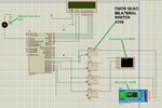
 

I don't know how to start, how to conect two module the bluetooth and rfid.
 

I don't know how to start, how to conect two module the bluetooth and rfid.

The fist step prior to start a new project is to list the general requirements in the optic of the hardware capabilities. Without deepen to much, don't you see that clearly there is no enough physical UART than required to interface with the modules ? Although being perfectly possible to implement a soft uart, I would not recommend it for you, therefore it's time to select another uC to do that.
 

The fist step prior to start a new project is to list the general requirements in the optic of the hardware capabilities. Without deepen to much, don't you see that clearly there is no enough physical UART than required to interface with the modules ? Although being perfectly possible to implement a soft uart, I would not recommend it for you, therefore it's time to select another uC to do that.

That's the problem i don't know how to conect the two modules i know how to conect juste one but not two, i don't know how to code in Mikroc and that's why i am lost and why i need your help.
 

i don't know
Seems there are a lot of lacks on your skills to deal with that, and no one can learn the required stuffs for you. Anyway, specifically answering the question and repeating what has already been said, select another uC than not the PIC16F877, and just connect TX form modules to RX of microcontroller, and vice-versa.
 

Hi,

What are the interfaces of the modules? And what are their signal lines?

Look for the same interface(s) on the microcontroller and connect the signal lines to the modules. Don´t forget to connect GND to ALL devices.

Take a pencil and a sheet of paper and draw the modules, the microcontroller and their connections.


Klaus
 
Seems there are a lot of lacks on your skills to deal with that, and no one can learn the required stuffs for you. Anyway, specifically answering the question and repeating what has already been said, select another uC than not the PIC16F877, and just connect TX form modules to RX of microcontroller, and vice-versa.

Yes i know i don't have skills for that, at first with one module exemple bluetooth a know how to conect i use UART conection and it works but here there are two modules and i have only one TX and RX, i was looking on the internet and i find SPI conection its say that i can conect 2 modules. But i dont know how to make it.
 

Hi,

What are the interfaces of the modules? And what are their signal lines?

Look for the same interface(s) on the microcontroller and connect the signal lines to the modules. Don´t forget to connect GND to ALL devices.

Take a pencil and a sheet of paper and draw the modules, the microcontroller and their connections.


Klaus

Bleutooth: HC-05
RFID: Q5M-005

The problem is, i know how to conect them but only one module at the time. i want to know how to conect the two modules at the same time.
 

Hi,

I don´t have the time to go to through the datasheets and find out what interfaces and connections to use. It´s your job.

Please answer the questions of post#7.


Klaus
 

Hi,

I don´t have the time to go to through the datasheets and find out what interfaces and connections to use. It´s your job.

Please answer the questions of post#7.


Klaus

i don't know how to use datasheets, so i don't know how to find the interfaces and connections.
It's true i don't have much skills and i don't know much about easyPIC but i hope somebody can help me.
 

Both using UART. Anyway, I'm also don't understand how we can help.

I know how to conect one module UART but not two if there are a way to conect two modules without using UART or using i will use it.
 

Considering that you have no knowledge in almost everything you asked here ( firmware, hardware, etc... ), do you really expect to achieve something ? We're repeatedly telling you that no one will do this job for you, but if you have specific question in specific topics, we'll be glad to help you.
 

Considering that you have no knowledge in almost everything you asked here ( firmware, hardware, etc... ), do you really expect to achieve something ? We're repeatedly telling you that no one will do this job for you, but if you have specific question in specific topics, we'll be glad to help you.

I don't ask you to do this job for me, i ask you to find me a exemple or some website or even a PDF file for helping me.
 

I have difficulties to hear a clear question, I can just guess that the problem is how to connect two modules with UART interfaces to a PIC16F877A that has only one UART port?

A simple way would be to switch to a more recent PIC type with two UARTs. Presuming you are tied to PIC16F877A, implementing a software UART would be another option. It has serious restrictions, e.g. you can't run interrupts (at least not interrupt functions consuming significant processing time) while sending or receiving through software UART.


Sorry for not being clear i have some difficultis with the english.
Ok i did a screenshot of what i did for now and i will put my code also, maybe it will be more clear.
Yes i want to make work two modules with one TX and RX with the UART conection.


The mikroC code:


Code C - [expand]
1
2
3
4
5
6
7
8
9
10
11
12
13
14
15
16
17
18
19
20
21
22
23
24
25
26
27
28
29
30
31
32
33
34
35
36
37
38
39
40
41
42
43
44
45
46
47
48
49
50
51
52
53
54
55
56
57
58
59
60
61
62
63
64
65
66
67
68
69
70
#define
 
sbit LCD_RS at RB4_bit;
sbit LCD_EN at RB5_bit;
sbit LCD_D4 at RB0_bit;
sbit LCD_D5 at RB1_bit;
sbit LCD_D6 at RB2_bit;
sbit LCD_D7 at RB3_bit;
 
sbit LCD_RS_Direction at TRISB4_bit;
sbit LCD_EN_Direction at TRISB5_bit;
sbit LCD_D4_Direction at TRISB0_bit;
sbit LCD_D5_Direction at TRISB1_bit;
sbit LCD_D6_Direction at TRISB2_bit;
sbit LCD_D7_Direction at TRISB3_bit;


void main() {
 
  ADCON1=7;
  INTCON.GIE=1;
  INTCON.T0IE=1;
  INTCON.T0IF=0;
  TRISD = 0;
 
  TRISA = 255;
  TRISC = 0;
  TRISD=0;
  UART1_Init(9600);
  
 
  Lcd_Init();                  
  Lcd_Cmd(_LCD_CLEAR);         
  Lcd_Cmd(_LCD_CURSOR_OFF);
  Lcd_out(2,1, "???");   
 
  Delay_ms(100);
  
  while(1) {


         if(doora.b0==1) {
                         UART1_write(48);                                                    
                         UART1_write(49);                    //0x01 + 0x0B + 0x03 + 0x01 + 0x00 + 0xC6 + 0x49 + 0x6F + 0xFF + 0x93 + 0x31
 
                         UART1_write(48);
                         UART1_write(66);
                         UART1_write(48);
                         UART1_write(51);
                         UART1_write(48);
                         UART1_write(49);
                         UART1_write(48);
                         UART1_write(48);
                         UART1_write(99);
                         UART1_write(54);
                         UART1_write(52);
                         UART1_write(57);
                         UART1_write(54);
                         UART1_write(102);
                         UART1_write(102);
                         UART1_write(102);
                         UART1_write(57);
                         UART1_write(51);
                         UART1_write(51);
                         UART1_write(49);  
 
                         delay_ms(2000);
                         }


The screenshot:
Captsqure.JPG
 
Last edited by a moderator:

Your code don't reflect anywhere what was received on serial port. Actually, there isn't any routine to get incoming bytes on the UART rx for the microcontroller; I would expect something like "UART1_read()" either on interrupt vector or in the while(1) loop.
 

Your code don't reflect anywhere what was received on serial port. Actually, there isn't any routine to get incoming bytes on the UART rx for the microcontroller; I would expect something like "UART1_read()" either on interrupt vector or in the while(1) loop.

Yes i did't finish it, that's why i ask you what should i put to controle the swich and the UART rx,tx.
 

what should i put to controle the swich and the UART rx,tx

I'm sure Compiler's website has a lot of templates to deal either with LCD and UART reception ( not to mention here on this forum ), did you even search there ? I'm not too motivated to write line by line here along with you. If you're not able to do that, it's time to learn a few more, not to code yet.
 

Status
Not open for further replies.

Similar threads

Part and Inventory Search

Welcome to EDABoard.com

Sponsor

Back
Top