Continue to Site

Welcome to EDAboard.com

Welcome to our site! EDAboard.com is an international Electronics Discussion Forum focused on EDA software, circuits, schematics, books, theory, papers, asic, pld, 8051, DSP, Network, RF, Analog Design, PCB, Service Manuals... and a whole lot more! To participate you need to register. Registration is free. Click here to register now.

dual voltage machanical switch

Status
Not open for further replies.

barg

Junior Member level 2
Joined
Feb 27, 2016
Messages
20
Helped
0
Reputation
0
Reaction score
0
Trophy points
1
Activity points
185
Hello to All,

I have two different vin lines 12v and 24v and I need a pushbutton switch that by pressing one time the output conductor will be 12v and pressing second time, the output will be 24v, pressing the third time the output will be not 12v and not 24v (neutral) some kind of on/off/on switch but not a toggle.

Now, I have found a 1no1nc push button switch and I am not sure it answer this question.

Appreciate if any of you experience fellows can advice what technical definition I need to look for to get the right pushbutton switch?

Regards
 

Hi,

...I'm not sure if this does carry out the function you require, on-none-on, but you could research this type online or contact RS to chat and check what this pushbutton actually does, or the manufacturer (RS are usually pretty good at directing you to the actual manufacturer for their parts when you have technical questions which their agents are occasionally unable to locate the info. for); at first sight it looks like it has three positions, best check first though.

https://uk.rs-online.com/web/p/push-button-switches/8200491/

https://uk.rs-online.com/webdocs/135c/0900766b8135c128.pdf
 

The concept for what you need is 1-of-3 selector. You push the button, it cycles the input (or clock input), which goes to a counter, flip flops, etc.

The 4017 IC (decade counter) rotates incoming pulses to 10 output pins in succession. You would only need to use 3 outputs. It's a good idea to add a debounce circuit.
 

Hi Brad,

Thanks for your advice, but I don't have room for additional circuit or pcb, tough I will take your advice for other uses. However, there is a solution using On Off On Rocker Switch for automotive use but I need it in push button and not Rocker and my basic question is a 1NO1NC push button can refer to the same method?

Regards
 

Hi,

Maybe this description of NO and NC pushbuttons can answer your question:

**broken link removed**

Maybe posting a link to the button you are talking about saves people guessing if it is suitable for the requirements. In principle, I think a 1NO-1NC can only do two things: Turn one set of contacts on and the other off, and vice versa, it would have no third "both off."

I believe I have already posted a link to a pushbutton that does carry out the function you specified, it has 6 contacts: 2 for 12V, 2 for 24V and 2 for "off."

You would also need to check that any button you eventually select is momentary or locking.
 

I don't think you will find a mechanical 3-way pushbutton to do what you want.
Thus you will need a momentary pushbutton and some added circuitry.
 
Last edited:

Thank you d123 for the thoughts and links which was useful but I must stick to my initial requirement so I will need to use some kind of a decoder ic for this output also like noted by Crutschow.

As to Brad's offer, its good idea but I need the other way of conducting, meaning to receive from two different inputs for 1 output on each push button pulse, I changed the design and put it into a logic schematic as attached to clarify, please advice if you know of an ic that can output exactly the input it receives like in the description (one time to work from this pin and one time from the other pin) SWITCH SWAP.png?

Thanks again
 

I have a torchlight with a sequential pushbutton (off-low-off-high), I know also multi-circuit residential light switches with sequential function. It could be that some vendor makes it in a form suitable for your purposes. But you'll probably have difficulties to find it.
 

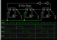
Flip-flops rotate incoming pulses in sequence to 3 outputs. When one output is On, the other two are Off.


The two inverters are not necessary in real life, but the simulation fails to change state without them for unknown reasons.
 

Flip-flops rotate incoming pulses in sequence to 3 outputs. When one output is On, the other two are Off.


The two inverters are not necessary in real life, but the simulation fails to change state without them for unknown reasons.
That circuit needs to be initialized.
If it powers up with all FF outputs low or all high they will all stay in that state.
 
That circuit needs to be initialized.
If it powers up with all FF outputs low or all high they will all stay in that state.

You are correct. Often my simulation misbehaves. Then I need to do something in an effort to restore proper operation. I might try connecting a wire to ground momentarily, etc.

I suspect that pullup/pulldown resistors are needed in strategic places.
 

Thank you all for your Assistance, I managed to change the spec so I don't need this kind of a switch.

Regards
 

You are correct. Often my simulation misbehaves. Then I need to do something in an effort to restore proper operation. I might try connecting a wire to ground momentarily, etc.

I suspect that pullup/pulldown resistors are needed in strategic places.
Typically an RC circuit is used to momentarily apply a pulse upon power startup to the appropriate set or reset input on the FFs.
In your circuit you could apply that pulse to two of the reset inputs, and one of the set inputs.
 
Status
Not open for further replies.

Similar threads

Part and Inventory Search

Welcome to EDABoard.com

Sponsor

Back
Top