Rahul Sharma
Member level 3
- Joined
- Sep 9, 2014
- Messages
- 63
- Helped
- 4
- Reputation
- 8
- Reaction score
- 4
- Trophy points
- 8
- Location
- Guwahati, INDIA
- Activity points
- 506
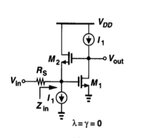
suppose any Voltage current feedback network is implemented and we have calculated its Aβ (loop gain) then how will i found its input /output impedance from this expression . Figure is given below for a reference
I have calculated Aβ as -gm1 ro1 {Rs gm / (1+ gm Rs)}
I have calculated Aβ as -gm1 ro1 {Rs gm / (1+ gm Rs)}