Continue to Site

Welcome to EDAboard.com

Welcome to our site! EDAboard.com is an international Electronics Discussion Forum focused on EDA software, circuits, schematics, books, theory, papers, asic, pld, 8051, DSP, Network, RF, Analog Design, PCB, Service Manuals... and a whole lot more! To participate you need to register. Registration is free. Click here to register now.

3 level triac AC dimmer

Status
Not open for further replies.

bmandl

Full Member level 4
Joined
Feb 26, 2010
Messages
207
Helped
3
Reputation
6
Reaction score
3
Trophy points
1,298
Location
Slovenia
Activity points
2,965
Hello.
I am designing light dimmer with 3 levels of brightness. I am doing this strictly in educational purpose, so I constructed digital circuit with flip flops and nand gates, which outputs digital signal on each press of a button to a 4 different outputs (one for each press). Now, I want to separate this circuit with optocouplers from triggering circuit with triac. 3 levels of brightness will be implemented with string resistor ladder and capacitor.
I need your help to calculate values of resistors and capacitor. At first stage, I want about 120° firing angle, second stage about 60°, third stage about 0° and fourth stage 180°. I can't find useful article on internet on how to calculate values of C and R. There are millions of made circuits with values written, but nowhere to find, how to calculate values for desired firing angle. Also, I don't fully understand how firing delay works with capacitor. Is there any study case, where everything is explained? IMG_0636[1].jpg
 

Find out what volt level causes the thyristor gate to trigger. (I built a light dimmer and
used a plain potentiometer to adjust triac firing. I found that it worked.)

The capacitor charges through the resistor. When it reaches trigger voltage, the thyristor fires.

Calculate what resistances will result in the desired charge times on the capacitor.
The waveform is not constant DC, so it makes your calculations complicated.

The gate needs sufficient current to trigger it. Your RC network needs to be capable of passing that much current.
 

Hi,

a lot of diacs fire at about 30V.

But you don´t give your AC input voltage, this makes it impossible to calculate values.

*****
When firing is delayed for 60°, then the voltage at the capacitor (slowly) rises until it reaches trigger point.
With a diac it is rapidly discharged to a specified value (see diac datasheet). Then it has additonal 120° time to discharge the capacitor. It won´t go to zero. Then the other halfwave starts with a non-zero voltage at the capacitor. Remember this when doing calculations.

This is worse when triggering at 120° delay. It has only 60° time to discharge.

Klaus
 

Thank you for your answers. But I just can't figure out, how to calculate resistors for required triggering angle. I assume it can not be done by hand, as it would include differential equations. I've been searching a lot, but it seems that every dimmer that has been made was either digital controlled via optocoupler, or nobody bothered calculating resistance. Just upper and lower angles, everything between is achieved with potentiometer.
 

Hi,

May I ask why you don't give the missing informations?

Klaus
 

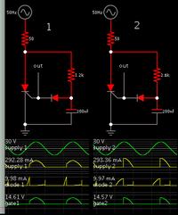
Simulators were made for this kind of situation. Taking the example in the Circuits menu...


I used an scr because Falstad's simulator does not have a triac model. Anyway an scr keeps things simple. The gate conducts 10mA. It triggers when it receives 50 percent of the supply V. Not all thyristors behave this way. Experimentation is required.

By increasing the R value of the RC network, you lengthen the turn-on delay. I tried but I could not make it trigger during the second half of the supply sinewave. This may require additional RC stages, a diac, etc.
 

Klaus, what missing information do you require? Ac voltage is 230V AC mains voltage.
 

Hi,

Klaus, what missing information do you require? Ac voltage is 230V AC mains voltage.

ALL informations. You gave none, besides 60° and 120°.

Yes, one of the most important is the mains voltage.

But if you want to trigger a triac at 60 or 120°, then for sure you need to know the triac´s trigger voltage.
and the diac trigger voltage.
With both values you then know the capacitor´s voltage.
With the capacitors´s voltage and the 60°/120° and the mains frequency you can calculate the time.
With those two value you can calculate the resistor

and so on...

Did you try to calculate it without values? ;-)

Klaus
 

Hello. Thank you for your answer. Would you be so kind and take a few minutes to show me the step-by-step calculations?
I don't know which triac and diac I will be using yet, but lets say diac breakout voltage is 30V and you select the triac data. Mains frequency is 50Hz.
Thank you
 

Hi,

let´s assume the capacitor is discharged to near zero voltage at zero cross.

* the mains voltage rises and current is flowing through the resistor.
* the same current is flowing through the capacitor and thus the voltage across the capacitor rises.
Assuming the capacitor is charging slowly...
* Then with rising mains voltage the voltage across the resistor rises
* the current through resistor and capacitor rises.
* the voltage_steep at the capacitor rises
* after the mains voltage peak (90°) the voltage drops and thus the current drops.
* While the voltage_steep decreases it is still positive, menas the voltage at the capacitor still rises (until the mains voltage drops below capacitor voltage.
* so there is a critical phase angle where it is impossible to tirgger the triac.

Some calculations:
Lets assume the diac triggers at 30V capacitor voltage (depends on diac VBO and triac gate volatge)
* 230V AC mains voltage means 325V peak voltage
* calculate critical phase angle: means when 230V sine voltage meets 30V: sin(phi) = 30V/325V --> phi = 5.29° symmetric: 180°-5.29° = 174,7°
(good, we are far away with the desired 120°)
* raw estimation of average mains voltage 0°, 30°, 60°, 90°, 120° => 0V, 162V, 281V, 325V, 281V => average about: 210V
* time for 120°: 360° = 20ms, --> 120° = 20ms/3 = 6.7ms
* average capacitor voltage dring 120°: 0V to 30V (but slowly rising at the end makes the average a bit higher that 15V.) Lets assume 17V.

***
Now I´ll take a 10nF capacitor. If the value is good or not, we will se later.
Calculate the average current that is needed to charge a 10nF capacitor from 0V to 30V within 6.7ms:
C = I * t / V => I = C * V / t = 10nF * 30V / 6.7ms = 44.8uA
calculating R: average voltage across R / I: (210V -17V) / 44.8uA = 4.3MOhm.

****
I just started a LTSpice simulation. (I recommend you to use it. It´s free)
It says 30V after 6ms,
and 34V at 120°

So my raw estimation was no too bad.

********
Result:
I´d choos a larger capacitor: maybe 10 times. Means 100nF.
Then the resistor needs to be 1/10 of the calculated value. = 430k

According reliabilty of the results:
I´d say we are very close, because the capacitor will start with a negative value, not at zero. Therefore it will take longer to reach 30V.
How much depends on the diac, and triac data.

But I think the values are a good point to start.

Klaus
 
  • Like
Reactions: bmandl

    bmandl

    Points: 2
    Helpful Answer Positive Rating
We quickly realize calculations become complicated because of:

* voltage constantly changing to the thyristor
* voltage constantly changing as it charges capacitor
* capacitor causes phase change
* different diacs (or neon bulbs) have different firing voltage

So that probably is the reason we don't see many examples of step-by-step calculations for operating a scr or triac.

We can attempt to calculate conditions from one milliSecond to the next, however we ought to base it on our observations as to how the components interact. We ought to try experiments (or simulations at least), when the supply is DC, when charging voltage is DC, when using a resistive divider to apply voltage to the gate, etc.
 

Thank you very much Klaus for comprehensive explanation. I went through your procedure and started to understand more clearly what is happening. I was drawing diagrams along the way. There are few incomprehensible things nevertheless for me:
  • First of those is a question, whether it is correct to use average values for calculations?
  • Second, how did you calculate average value of voltage on capacitor from 0 to 30V. In fact, this voltage is not sinusoidal, rather it's a mix of exponential functions, with mains voltage rising (and) falling, until capacitor voltage reaches diac breakdown voltage. Am I right?
  • Thirdly, why did you say, that capacitor will start with negative voltage?
  • And my fourth question: When break-over happens, capacitor is discharged through diac and gate of a triac. But this discharging doesn't happen suddenly. Am I right? So when triggering angle is very big, close to upper limit of allowed angle, capacitor doesn't have enough time to fully discharge until the zero crossing. So it starts with some voltage on it (positive or negative). How can we consider this happening in our calculations? And this question somehow refers to previous question -> probably this is what you meant, when you said that capacitor will start with negative voltage.
Sorry, that I am being precise. It doesn't mean that I want to build accurate dimming, I am just curious. Things that I don't understand, bothers me.
Thank you again
 

Hi,

* Average values:
For a raw estimaton it worked fairly good.
But for precise values you need to integrate (V_mains - V_capacitor) over time.
(all my the above calculations are mental arithmetics, mo calculator. But I´m sorry I can´t do the complete integration by mental arithmetics :-( )

* Average capacitor voltage:
if the voltage rises linearely then the average 0V..30V is 15V. But we know that it rises fast at first, then it becomes slow. Therefore the true average voltage is a bit more than the 15V.
How much? I don´t know. But it doesn´t matter much, because the precision is dominated by the mains voltage.

* Capacitor negative voltage:
I did just an estimation for the positve halfwave. Now try to imagine what´s the voltage of the capacitor at exactely 180°. There is a relative fast discharge when the diac triggers, but not to 0.0V...then the diac releases. But I don´t know how much voltage remains after the diac releases. Additionally the resistor discharges the capacitor all the time between ignition and zero cross. But for these 30° I don´t think it comes very close to 0V. I estimate 2V ...5V. No guarantee.

* Capacitor discharge via diac:
Not suddenly, wut within a few microseconds. I think this is fast enough.
And: YES, this is what i meant with "it starts with negative capacitor voltage".
Indeed the positive mains halfwave starts with negative capacitor voltage
and the negative mains halfwave starts with positve capacitor voltage. I assume it is very symmetric.

* Precise:
I like it precise. And I like if somebody wants to know about the details that generate uncertainties, errors.. and so on.
Sooner or later when you work with electronic you come to the point where those details come into account. Then it´s good to know beforehand why something happens.. an usually it´s more easy to
avoid those erros.


Klaus
 
  • Like
Reactions: bmandl

    bmandl

    Points: 2
    Helpful Answer Positive Rating
Status
Not open for further replies.

Similar threads

Part and Inventory Search

Welcome to EDABoard.com

Sponsor

Back
Top