Continue to Site

Welcome to EDAboard.com

Welcome to our site! EDAboard.com is an international Electronics Discussion Forum focused on EDA software, circuits, schematics, books, theory, papers, asic, pld, 8051, DSP, Network, RF, Analog Design, PCB, Service Manuals... and a whole lot more! To participate you need to register. Registration is free. Click here to register now.

IR2153 + regulation and protection, modification, calculating the values

Status
Not open for further replies.

Mnt

Member level 5
Joined
Mar 20, 2016
Messages
91
Helped
2
Reputation
4
Reaction score
2
Trophy points
8
Activity points
721
HI there,

I modified this circuit

ir2153_simetrik_smps.gif

to this

simetrik.PNG

and need help calculating the values for the protection and for the feedback because I tried the feedback and it outputs me only 2-3 volts instead 23V as I wanted.

For the power im confused because there are a lot of power types -> peak power, rms power, average power, bla bla .. etc..

I need 250W limit.

Need some moderator to change my thread's title to -> "IR2153 + regulation and protection but need help calculating the values" :bsdetector:

----

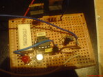
look at my current setup but this was before i soldered the opto + 220 ohm + 2k2 + TL431
and the 2V out ..
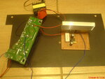
DSC05790.JPG

also im using gate stoppers unlike in the sch.
 
Last edited:

Re: IR2153 + regulation and protection but need help calculating the values

Is this calculation right for the power ?
Or I need to calculate with the rms voltage value -> 111V ?

314V/2 = 157V peak at the transformer

250W/157V = 1,5923566878980891719745222929936 amperes.
or
250W/111V = 2,2522522522522522522522522522523 amperes.

these 1.6 amperes * 0.47 ohm = 748,40764331210191082802547770671 mV
or
these 2.3 * 0.33 = 743,24324324324324324324324324324 mV

just enough to turn on a transistor. also beta varies a lot for a bc547 and i dont know what beta to use for my calculation :(

these milivolts * these amperes = 1,1917319161020731064140533084497 Watts Pd for this 0.47 resistance. => 2W resistor would suit nice.
or
these milivolts * these amperes = 1,6739712685658631604577550523494 Watts Pd for this 0.33 reisistance. => 2W resistor would suit nice.

----------------

I dont know how many ma i need to sink from pin 3 for the protection and for the feedback, its so confusing :(

- - - Updated - - -

I am wondering why this sch have an extra resistor EnnVF_li.jpg

Why not use only R6 but higher value ?

- - - Updated - - -

this good ?

this.PNG

- - - Updated - - -

What happens when the frequency exceed the maxium of the optocoupler ?
Im asking because the frequency of the fb loop is unlimited hz-es.
Do I need to limit it with low pass filter ?
 

You need to multiply all your calculations with a factor of 3,6739712685658631604577550523494. Enjoy.
 

R6 is there to bypass some optoisolator current, in an effort to reduce aging. If I remember correctly, the aim is 2 to 5 mA.
However the zener requires about 10 mA to be above the knee.

These are ballpark values, I've not seen the data sheets.
 
  • Like
Reactions: Mnt

    Mnt

    Points: 2
    Helpful Answer Positive Rating
What happens when the frequency exceed the maxium of the optocoupler ?
Im asking because the frequency of the fb loop is unlimited hz-es.
Do I need to limit it with low pass filter ?
TNY266 is a simple hysteretic voltage controller which doesn't need (and won't take advantage from) loop compensation.

These are ballpark values, I've not seen the data sheets.
"Ballpark values" describes best the achieved regulator performance if you consider the rather loose Z-diode specification. But you can still make it worse by unsuitable component dimensioning. The TNY266 datasheet circuit should be a good starting point.

By the way, one of the first things you learn when doing hand calculations in engineering or natural science is to use appropriate number precision for a specific problem. You have rarely more than three or four significant digits.
 

Thanks friends, i will post again soon :)

By the way, one of the first things you learn when doing hand calculations in engineering or natural science is to use appropriate number precision for a specific problem. You have rarely more than three or four significant digits.

Heheh, it was a joke :D

- - - Updated - - -

R6 is there to bypass some optoisolator current, in an effort to reduce aging.
Ok :)
However the zener requires about 10 mA to be above the knee.

Look i found this but there are no such knee grafix in zener datasheets :( :O
-> https://electronics.stackexchange.c...w-does-r5-bias-the-zener-in-this-smps-circuit

And because there no such information i dont know what happens if im using 2ma zener current instead this 10 ma one.

---

Also i suppose 8 mA are enough to shutdown the IR2153 through stopping its oscillator via 3rd pin, Am I right ?
Is there such data in IR's datasheet ?

---

Also I still dont know what to use for the calculations Rms voltage 111 volts or peak voltage 314/2 ?

Also what is better supply source for the feedback -> before or after the filtration ?
 

Regulation works fine but now i have more questions.

It works better when the opto short-circuites the oscillator (pin 3) but this lowers the frequency to 8khz (stable, measured with multimeter at the gate of the oneth fet).
Original freq is 50khz.
Im wondering what will happen if i increase the frequency not the current ?
or Is this from lack of opto sink current (small opto collector current) resulting in lowering the capacitance of the osc -> lowering the frequency ?

It works normal freq when i kill the supply current of the IC with the opto and an additional bc556 instead pin 3 method but there is a ripple and the regulation is not good this way. :)

Do PC817 have 100% CTR ? If this is true this means that it sinks only 2.5 mA in my case and I need opto like TLP521.

Also There are loud noise (pitch or oscilation) when i attach a chinese class d amp to it. -> https://www.youtube.com/watch?v=phoUtZsC3AU
 
Last edited:

Also i forgot to mention that the regulation of the video is not good, now is rock solid.

Also when i mentioned "ripple" This ripple was only without load. This is strange.
 

This is my progress friends but im having PC817 instead TLP521. Is there a difference between these ?
Also I can connect to pin 3 or to kill the supply, Im very confused.

Also suddenly smth went wrong when it was working and now both mosfets are dead.
This happened with lamp in the mains for protection :O This is very weird and strange.
Do I need to have a RC snubber in the primary ?
Is this the reason, a HV spark ? :fight:

I have short circuited so many times and it was a living soul (it wasnt a problem, the lamp saved the circuit many times).
having.PNG
 
Last edited:

Thanks friends, i will post again soon :)


And because there no such information i dont know what happens if im using 2ma zener current instead this 10 ma one.

The information does exist. It is the component datasheets.
The parameter you should be looking for is Vz @ Izt (Zener voltage at a specified test current).
 
  • Like
Reactions: Mnt

    Mnt

    Points: 2
    Helpful Answer Positive Rating
Ok I was searching for grafix, what about the other questions ?
Where to attach the opto -> before or after the LC filter ?
 

Hello, anybody here ? Nobody is answering. :thumbsdown:

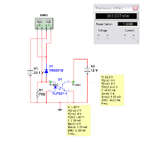
I tried to estimate the protection with this simulation but the power is moving non stoppable. 70 wats, 90 wats, 150 wats, .. This makes it impossible to estimate. Is my pc slow for the simulation or what ?

The zener diode is 15.6 volt like in the IC. I want constant 125W measure at the wattmeter and 1.8 volts (the led voltage drop) at the zener diode.

protect_.PNG
 

UPDATE

IM DONE with the regulation.

This is the way im doing it -> yes.PNG
Its a twist with this mosfet and an additional beta enhancer but this is the way to work silent ( i mentioned its audible without this mosfet) :D.

Im very happy because I've never seen a schematic with IR2153 and voltage regulation.
Im an inventor momma, people thinked its impossible to make a regulation with this chip :D

- - - Updated - - -

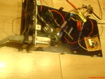
DSC05813.JPGDSC05814.JPGDSC05815.JPG
 

Im done with the protection but there are still unanswered questions..
This prot is for 240W limiting.

**broken link removed**
 

What are your questions?

The current limiting circuit you've got is extremely wasteful. By the time you account the voltage drops of the bridge and the optocoupler's led, there will be perhaps 3 volts across R3. You'll be losing well over 10 watts there.

One of the things that I deeply dislike about Multisim, is its ability to make even the simplest schematic utterly confusing.
Your schematic is not that bad.
But the other day there was this "dude" who designed an audio amplifier, and became all upset whenever many people pointed to him that it was impossible to understand his schematic.

But you could help us all, by at least removing the virtual instruments when you post an image.
 

I have 2 questions left:
1.what is better supply source for the feedback -> before or after the filtration ?
2.(for the regulation)what about increasing frequency and removing the bs170 mosfet. Its audible without this mosfet but what will happen if i increase frequency. Is it possible to have a moment in which the frequency goes more than 50khz (i dont want that to happen)?

"The current limiting circuit you've got is extremely wasteful. You'll be losing well over 10 watts there."

Why 10 watts ? Multisim tells me a wattage under 5W and a 5W resistor would suit me.
 

Status
Not open for further replies.

Similar threads

Part and Inventory Search

Welcome to EDABoard.com

Sponsor

Back
Top