Continue to Site

Welcome to EDAboard.com

Welcome to our site! EDAboard.com is an international Electronics Discussion Forum focused on EDA software, circuits, schematics, books, theory, papers, asic, pld, 8051, DSP, Network, RF, Analog Design, PCB, Service Manuals... and a whole lot more! To participate you need to register. Registration is free. Click here to register now.

MOSFET gate current calculation

Status
Not open for further replies.

francis29

Member level 5
Joined
Mar 22, 2016
Messages
90
Helped
2
Reputation
4
Reaction score
3
Trophy points
8
Location
India
Activity points
721
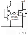
I want to use a mosfet for switching power supply.
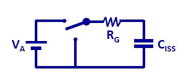
I want to know how much current gate will source/sink? I am getting the PWM from a microcontroller. Can i directly connect the mosfet gate to the microcontroller or i have to use specific driver?
Is there any formula to calculate gate current?
 

The DC gate current is zero but the AC gate current depends on the gate capacitance (listed in the datasheet, it takes AC current to charge and discharge this capacitance) and frequency.
Maybe you need a complementary pair of emitter-followers to provide enough gate current:
 

Attachments

  • Mosfet driver circuit.PNG
    Mosfet driver circuit.PNG
    9.3 KB · Views: 138
MOSFET gate is purely capacitive load, gate current will be limited by the driver and preferably by an additional series resistor. The resistor will be chosen so that you keep the controller maximum output current rating.

Gate current limiting slows down MOSFET switching time according to the gate charge (see MOSFET datasheet). If you want fast switching with a large MOSFET (= large input gate capacitance and gate charge), you need a dedicated MOSFET driver. Also when the 3.3 or 5V µC output voltage is insufficient to turn your MOSFET fully on.
 
A "logic level" Mosfet (example IRL540) works when the gate voltage is 4.0V to 10V. An ordinary Mosfet (example IRF540) needs a gate voltage of 10V to 15V for it to completely turn on.
 
Is there a direct formula to find out the gate current requirement?
 

The question is badly asked: you need to give the details of the application for a meaningful answer.

As the gate drive is mostly capacitive, a small current will take long time to switch on. A high current will turn on the device fast.

You need to decide the time you want the device to turn on hard: Then the question will be how much current you will need to charge a capacitor (for value, look up the datasheet) to 12V (say) in xyz u secs.

Fast turn on reduces losses due to switching; again your driver must be able to sink current because the device also need to be turned off fast.

It is good to use a simple driver because most microcontrollers will not be able to output (source/ sink) 12-15V directly with sufficient current capacity
 

Hi,

As said before: the gate acts as a capacitor:

Then the formula is: I = C × dU / dt.

This is true as long as the voltages at source and drain are constant.
But for example with low side switching...there is a time where drain voltage moves..you need to split the current paths.
One is the gate to source current, the other is the gate to drain current.

On details read about the miller effect.

Klaus
 

Every time the fet gets switched on…the gate goes up to a voltage Vdrive. And the energy in the gate cap (CISS) is 0.5*C*Vdrive*Vdrive
= 0.5 * Qg * Vdrive

So the power drawn for the gate drive is 0.5*Qg*Vdrive*fsw.

The total gate drive current is I = Q/t

So its I (drive) = Qg * fsw

Qg is in the datasheet

Usually there is a small resistor in series with the gate drive that limits the rush current. Everytime the fet is switched on the gate goes to the voltage Vdrive exponentially determined with a time constant determined by the series resistance and the gate capacitance.

We can calculate the 90% values but not the 100% values. The same applies to the turn off.

If the series charging (or discharging) resistor is skipped, the voltage goes up instantly but there will be some other factors that will prevent an infinite current at turn on. So it is good to have the series resistor to have a predictable current. That will also reduce device dependence.
 
  • Like
Reactions: CataM

    CataM

    Points: 2
    Helpful Answer Positive Rating
Yes good point, i must admit i misread the original qu and thought OP was asking about the average current used in driving the gate of the FET.
i now have read again and realise that OP wants to know about instantaneous gate drive current.
Well yes, at the gate threshold voltage (which is where the voltage is fairly well clamped to during the most of the switching transition) you can get this currnt by ohms law..........I drive = (vdrive-Vth)/R series

The R series being as described by C__Mitra.

As you know , you have to adjust the Vth depending on whether in the miller region, or the other bit ewhich happens near the actual gate thresh voltage.....as you know, the miller plateau is at Vth + i(peak)/transconductance...this is as per the document on high speed gate drives by Laszlo Balogh
 

Your circuit looks like this


So the max current is Vapplied/Rg and then exponentially goes to 0.
 

Status
Not open for further replies.

Similar threads

Part and Inventory Search

Welcome to EDABoard.com

Sponsor

Back
Top