Continue to Site

Welcome to EDAboard.com

Welcome to our site! EDAboard.com is an international Electronics Discussion Forum focused on EDA software, circuits, schematics, books, theory, papers, asic, pld, 8051, DSP, Network, RF, Analog Design, PCB, Service Manuals... and a whole lot more! To participate you need to register. Registration is free. Click here to register now.

How to increase brightness on multiplexed 7 segments?

Status
Not open for further replies.

Ma3ix

Member level 2
Joined
Dec 17, 2015
Messages
43
Helped
0
Reputation
0
Reaction score
0
Trophy points
6
Activity points
375
Hi,
I have problem with brightness on 7 segment display CC.
The problem is when I use smaller delay in loop (for example 5ms), brightness of displays dramatically reduce. For bigger delay (100ms) brightness is fine but then I got flickering.
How can I increase brightness without flickering?

Here is schematic. With this configuration I have about 14mA segment current which should be fine :?:
Im using this display : https://www.alldatasheet.com/datasheet-pdf/pdf/233015/KINGBRIGHT/SC52-11EWA.html
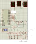
brightness.JPG
 

Don't put the display control routine within the main loop. Use a timer interruption activated flag to determine the timing. The better solution is the PWM output, but for this you should add a PNP transistor in series with all segments.
 
  • Like
Reactions: Ma3ix

    Ma3ix

    Points: 2
    Helpful Answer Positive Rating
Don't put the display control routine within the main loop. Use a timer interruption activated flag to determine the timing. The better solution is the PWM output, but for this you should add a PNP transistor in series with all segments.

All segments? 3 displays * 8 = 24 pnp tranzistors or 8 transistors?

Can you explain me why using ISR can increase brightness or why using waitms in loop reduce it? Timing problem?
 

I'm assuming you are putting delay commands in the isr vector and are controling display in the main program, but it is in fact just a guess and my assumption may be totally wrong. Unless you show your code, you'll not get a precise answer.
 

I'm assuming you are putting delay commands in the isr vector and are controling display in the main program, but it is in fact just a guess and my assumption may be totally wrong. Unless you show your code, you'll not get a precise answer.
Here is the part of code used for multiplexing written in Bascom. As I said, everything works fine with bigger delay in Waitms(example 100 ms)
Code:
'$sim
$regfile = "REG51.DAT"                                        ' specify the used micro
$crystal = 12000000                                           ' used crystal frequency
                                              
---variables----
Tran1 Alias P1.0                                              
Tran2 Alias P1.1                                              
Tran3 Alias P1.2
Disp Alias P2                                                                     '
------------------
Do                                                            

Bi = Vou1 / 100                                               
Gosub Convert
Set Tran1                                                     
Disp = Bi
Waitms 5
Reset Tran1
Waitms 5


X = Vou1 / 10
Bi = X Mod 10
Gosub Convert                                                 
Set Tran2                                                     
Disp = Bi
Waitms 5
Reset Tran1
Waitms 5

Dim Y As Integer
Y = Vou1
Y = Y Mod 100                                                 
Bi = Y Mod 10
Gosub Convert                                                 
Set Tran3                                                     
Disp = Bi
Waitms 5
Reset Tran3
Waitms 5

Convert:                                                      'convert data to seven segment format
   Select Case Bi
      Case 0 : Bi = &H3
      Case 1 : Bi = &HCF
      Case 2 : Bi = &H24
      Case 3 : Bi = &H84
      Case 4 : Bi = &HD8
      Case 5 : Bi = &H90
      Case 6 : Bi = &H10
      Case 7 : Bi = &HC7
      Case 8 : Bi = &H0
      Case 9 : Bi = &H80
   End Select
Return

Loop

End
 

Your code has no comments, which turns hard to understand without knowing the meaning of each variable.
 

Hi,

14mA is fine....

I´m not sure...
With a 1:3 multiplex rate you should use 3 x 14mA..
(I assume your multiplex rate is 1:3 and the recommended DC current of each segment is 14mA)

The total high side drive current goes then up to 3(ratio) x 14mA x 7(segments) = about 300mA


Klaus
 

Your code has no comments, which turns hard to understand without knowing the meaning of each variable.

Code:
'$sim
$regfile = "REG51.DAT"                                        ' specify the used micro
$crystal = 12000000                                           ' used crystal frequency
                                              
---variables----
Tran1 Alias P1.0      ' Tran1,Tran2,Tran3 -->NPN transistor used for switching the displays                                             
Tran2 Alias P1.1                                              
Tran3 Alias P1.2
Disp Alias P2         ' Segments of displays conncected to PORT2                                                            '
------------------
Do                                                            

Bi = Vou1 / 100         ' display ones of Vou1                                      
Gosub Convert
Set Tran1                                                     
Disp = Bi
Waitms 5               'delay of 5 miliseconds
Reset Tran1
Waitms 5


X = Vou1 / 10          ' display tens of Vou1
Bi = X Mod 10
Gosub Convert                                                 
Set Tran2                                                     
Disp = Bi
Waitms 5
Reset Tran1
Waitms 5

Dim Y As Integer     ' display hundreds of Vou1
Y = Vou1
Y = Y Mod 100                                                 
Bi = Y Mod 10
Gosub Convert                                                 
Set Tran3                                                     
Disp = Bi
Waitms 5
Reset Tran3
Waitms 5

Convert:                              'convert data to seven segment format
   Select Case Bi
      Case 0 : Bi = &H3             ' display zero 
      Case 1 : Bi = &HCF           'display one
      Case 2 : Bi = &H24            'etc...
      Case 3 : Bi = &H84
      Case 4 : Bi = &HD8
      Case 5 : Bi = &H90
      Case 6 : Bi = &H10
      Case 7 : Bi = &HC7
      Case 8 : Bi = &H0
      Case 9 : Bi = &H80
   End Select
Return

Loop

End

- - - Updated - - -

Hi,

14mA is fine....

I´m not sure...
With a 1:3 multiplex rate you should use 3 x 14mA..
(I assume your multiplex rate is 1:3 and the recommended DC current of each segment is 14mA)

The total high side drive current goes then up to 3(ratio) x 14mA x 7(segments) = about 300mA


Klaus


Im not sure about this? This leads to the questionnaire the whole idea of multiplexing.. Cause brightness (current of 14mA) is good for bigger delay of switching
 

Your questions still lacks of more explanations, as for example the fact that you mentioned the impact of changing from 5ms to 100ms delay, but there are 3 lines where you call 'Waitms 5'. Should we assume your changed simultaneously all these lines ?

Another unmeaning things on your code:

Display units: Set Trans1 / Reset Trans1
Display dozens: Set Trans2 / Reset Trans1
Display houndreds: Set Trans3 / Reset Trans3

What is the logic behind that switching ?
 

Your questions still lacks of more explanations, as for example the fact that you mentioned the impact of changing from 5ms to 100ms delay, but there are 3 lines where you call 'Waitms 5'. Should we assume your changed simultaneously all these lines ?


Another unmeaning things on your code:

Display units: Set Trans1 / Reset Trans1
Display dozens: Set Trans2 / Reset Trans1
Display houndreds: Set Trans3 / Reset Trans3

What is the logic behind that switching ?

1)
It is just for example, with 5 miliseconds delay i have problem with brightness, if I replace code with Waitms 100 miliseconds Then I have problem with flickering (brightness is better).. Brightness & Flickering =inversely proportional

2)
Set Trans1- put pin P1.0 HIGH (turn on display 1)
waitms5 (wait 5 miliseconds)
Reset Trans1 - put pin P1.0 LOW (turn off display 1)
waitms5 (wait 5 miliseconds)
 

Hi,

This leads to the questionnaire the whole idea of multiplexing.. Cause brightness (current of 14mA) is good for bigger delay of switching
* Don´t expect higher brightness with multiplexing
* Don´t expect lower overall current with multiplexing
* multiplexing needs less port pins and eases wiring.

Klaus
 

"the whole idea of multiplexing"...

The idea of multiplexing is to share the available display time equally between the used digits (e.g. three in your design) and to minimize dead time with all digits off. Respectively you want moderate delays (short enough to avoid flickering, e.g. several milliseconds) during digit on-time and very short delays (e.g. some microseconds) during off-time.

Displays have specifications for average and peak current. With three digits, you can usually the increase the peak segment current by a factor of three without exceeding the permitted peak current, so that the average current and respectively the display brightness is roughly maintained compared to non-mux drive.
 
  • Like
Reactions: Ma3ix

    Ma3ix

    Points: 2
    Helpful Answer Positive Rating
"the whole idea of multiplexing"...

The idea of multiplexing is to share the available display time equally between the used digits (e.g. three in your design) and to minimize dead time with all digits off. Respectively you want moderate delays (short enough to avoid flickering, e.g. several milliseconds) during digit on-time and very short delays (e.g. some microseconds) during off-time.

Displays have specifications for average and peak current. With three digits, you can usually the increase the peak segment current by a factor of three without exceeding the permitted peak current, so that the average current and respectively the display brightness is roughly maintained compared to non-mux drive.

Max peak forward current for this 7-segment:
https://www.alldatasheet.com/datasheet-pdf/pdf/233015/KINGBRIGHT/SC52-11EWA.html

is 160 mA at 1/10 Duty Cycle, 0.1ms Pulse Width. How can I increase it for this configuration (shematic showed in first post)?
Thanks
 

You need to reduce the 330 ohm resistors, possibly also base resistors, use "stronger" digit driver transistors (higher current gain at 500 to 800 mA).
 
  • Like
Reactions: Ma3ix

    Ma3ix

    Points: 2
    Helpful Answer Positive Rating
Hi,

Lower the resistance of R1..R7.
I also recommend to replace Q1..Q3 with mosfets. Rdson smaller than 1 Ohm and logic level drive.

Klaus
 
  • Like
Reactions: Ma3ix

    Ma3ix

    Points: 2
    Helpful Answer Positive Rating
Ok thanks. First I will try with lower resistors on segments..

The datasheet says max. DC forward current is 30mA, so I must not exceed that value,correct?
 

DC means continuous current. 50 or 60 mA should be well acceptable for 1:3 mux.
 

Another possibility is increasing the contrast ratio by placing a piece of the ubiquitous "red plastic" in front of the LEDs and blocking all external ambient light from between the plastic and the LEDs.

That will create a very dark background, even in high ambient light, and make the lit segments appear much brighter.
 
  • Like
Reactions: Ma3ix

    Ma3ix

    Points: 2
    Helpful Answer Positive Rating
You need to reduce the 330 ohm resistors, possibly also base resistors, use "stronger" digit driver transistors (higher current gain at 500 to 800 mA).

Replaced 330 with 150 Ohms and nothing significant has changed:thinker:

- - - Updated - - -

Another possibility is increasing the contrast ratio by placing a piece of the ubiquitous "red plastic" in front of the LEDs and blocking all external ambient light from between the plastic and the LEDs.

That will create a very dark background, even in high ambient light, and make the lit segments appear much brighter.

it is good idea and a very practical solution:clap:..On second thought, the manufacturer should consider that idea.

I still need some more electric engineering solution:?:
 

Hi,

maybe it´s time to give an updated schematic...

Klaus
 

Status
Not open for further replies.

Similar threads

Part and Inventory Search

Welcome to EDABoard.com

Sponsor

Back
Top