Continue to Site

Welcome to EDAboard.com

Welcome to our site! EDAboard.com is an international Electronics Discussion Forum focused on EDA software, circuits, schematics, books, theory, papers, asic, pld, 8051, DSP, Network, RF, Analog Design, PCB, Service Manuals... and a whole lot more! To participate you need to register. Registration is free. Click here to register now.

ACS712 - 30A interface with Arduino UNO

Status
Not open for further replies.

imranahmed

Advanced Member level 3
Joined
Dec 4, 2011
Messages
817
Helped
3
Reputation
6
Reaction score
3
Trophy points
1,298
Location
Karachi,Pakistan
Activity points
6,492
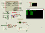
Please let me know that I want to interface ACS712-30A with arduino to measure

DC current in mA.

I have break light bulb of 2 filaments one is 18W and other is 5W.

for 18W @ 12VDC:
I=P/V = 18/12 = 1.5 A

for 5W @ 12VDC:
I=P/V = 5/12 = 0.416 A

But it cannot measure properly.

I used the code below from internet,

Code:
/*
Measuring Current Using ACS712
*/
const int analogIn = A0;
int mVperAmp = 66;          // 66 for 30A Module
int RawValue= 0;
int ACSoffset = 2500; 
double Voltage = 0;
double Amps = 0;

void setup(){ 
 Serial.begin(9600);
}

void loop(){
 
 RawValue = analogRead(analogIn);
 Voltage = (RawValue / 1024.0) * 5000; // Gets you mV
 Amps = ((Voltage - ACSoffset) / mVperAmp);
 
 
 Serial.print("Raw Value = " ); // shows pre-scaled value 
 Serial.print(RawValue); 
 Serial.print("\t mV = "); // shows the voltage measured 
 Serial.print(Voltage,3); // the '3' after voltage allows you to display 3 digits after decimal point
 Serial.print("\t Amps = "); // shows the voltage measured 
 Serial.println(Amps,3); // the '3' after voltage allows you to display 3 digits after decimal point
 delay(2500); 
 
}
 

Hi,

There was no error occured.

I tested with ampere meter it shows proper Bulb current i.e 1.48A , 1.5A for 18W filament and 0.41A for 5W

filament but when tested with Arduino Serial Monitor it shows 2.432A sometime 1.032A but cannot show

proper reading.
 

If your readings are fluctuating, it means that the voltage at the ADC is fluctuating as well.
Make sure that the supply to the ACS712 is clean and doesn't contain any noise, else it will vary the DC offset (i.e 2.5V) as well, causing an error in the reading.
If the supply is OK, then you can try adding a RC Filter at the output of CT and then pass the signal to the ADC.

Also, is your current going to go up to 30A? If not, then you may have had a poor choice of the CT, you could have settled to a ACS712-5/ACS712-20 for better sensitivity over your entire operating range.
 
You defined variable ACSoffset as being exactly 2500, but this sounds an "ideal" parameter, that should actually be determined by calibration ( e.g measuring baseline without any input ). There is proper IIR filtering techniques to take the average values from mean in order to dynamically shift the offset accordingly.
 

Before you attempt to measure with any microcontroller, measure the ACS712 voltage output with a multimeter to determine whether you are getting good readings or not.
 

Thank you,

How to select proper values of RC filter?

I am not using Current Transformer but using ACS712-30A.
 

You still haven't answered our questions.
If you measure with a DMM, or better still, with an oscilloscope, what do you read?
 

Hi,

@schmitt trigger,

The voltage is 4.97V at supply pins of ACS712 and 2.48V.

But how to fix at constant voltage of 5V and output 2.5V when no current pass?
 

Hi,

Maybe the break lights are pulsed with PWM...maybe this causes the unstable current reading.

Maybe, maybe .....we can't know.

If you need further help please post your schematic.

Klaus
 

If your readings are fluctuating, it means that the voltage at the ADC is fluctuating as well.
Make sure that the supply to the ACS712 is clean and doesn't contain any noise, else it will vary the DC offset (i.e 2.5V) as well, causing an error in the reading.
If the supply is OK, then you can try adding a RC Filter at the output of CT and then pass the signal to the ADC.

Also, is your current going to go up to 30A? If not, then you may have had a poor choice of the CT, you could have settled to a ACS712-5/ACS712-20 for better sensitivity over your entire operating range.


Only valid thing i have read so far on this during my research for same issue.

its very unreliable when using arduino with usb, because codes take ideal 5 volts into consideration, while in real world this dosent happen, and thus the readings fluctuate. I have tried and made this work, now all aspects of sensors and formulas are taken from current voltage, which are measured by secret arduino voltmeter.

It worked for me, if someone coding expert can also look and verify. I made everything dependent on voltage. Only modification credit goes to me, all else is available on internet.

https://inoace.com/blog/acs712-current-sensor-practical-formula/

or

Code:
/*
Code modified by arif from inoace.com, All credit goes to original authors, apart from modifications, of readings to be dependent on current voltage and not ideal 5 volts

*/

float vcc = 0;

void setup() {
Serial.begin(9600);
}

void loop() {
vcc = readVcc() / 1000.0;
Serial.print(“Vcc: “);
Serial.print(vcc);

long average = 0;
for (int i = 0; i < 100; i++) {
average = average + analogRead(A0);
delay(1);
}
average = average / 100;

float sensorValue = average * (5.0 / 1023.0);
Serial.print(” sense: “);
Serial.print(sensorValue, 3);

float acoffset = vcc / 2.0;
Serial.print(” offst: “);
Serial.print(acoffset, 3);

float sensitivity = 0.185 * (vcc / 5.0);
Serial.print(” sensi: “);
Serial.print(sensitivity, 4);

float amps = (sensorValue – acoffset) / sensitivity;
Serial.print(” Amperes: “);
Serial.print (amps);
Serial.println(“…”);
delay(1000);
}

long readVcc() {
// Read 1.1V reference against AVcc
// set the reference to Vcc and the measurement to the internal 1.1V reference
#if defined(__AVR_ATmega32U4__) || defined(__AVR_ATmega1280__) || defined(__AVR_ATmega2560__)
ADMUX = _BV(REFS0) | _BV(MUX4) | _BV(MUX3) | _BV(MUX2) | _BV(MUX1);
#elif defined (__AVR_ATtiny24__) || defined(__AVR_ATtiny44__) || defined(__AVR_ATtiny84__)
ADMUX = _BV(MUX5) | _BV(MUX0);
#elif defined (__AVR_ATtiny25__) || defined(__AVR_ATtiny45__) || defined(__AVR_ATtiny85__)
ADMUX = _BV(MUX3) | _BV(MUX2);
#else
ADMUX = _BV(REFS0) | _BV(MUX3) | _BV(MUX2) | _BV(MUX1);
#endif

delay(2); // Wait for Vref to settle
ADCSRA |= _BV(ADSC); // Start conversion
while (bit_is_set(ADCSRA, ADSC)); // measuring

uint8_t low  = ADCL; // must read ADCL first – it then locks ADCH
uint8_t high = ADCH; // unlocks both

long result = (high << 8) | low;

result = 1125300L / result; // Calculate Vcc (in mV); 1125300 = 1.1*1023*1000
return result; // Vcc in millivolts
}
 

lol, i just linked to my blog in an answer, and just read afterwards , that its against rules to link to blogs ?

pardon me.
 

lol, i just linked to my blog in an answer, and just read afterwards , that its against rules to link to blogs ?

pardon me.

Hi - Forum rules request that a post give the entire answer within the post, rather than giving a link. This makes it as convenient as possible for readers so they do not have to navigate to external websites. In addition the rules request that advertising-related blogsites be posted in the Business-Promotions-Advertising section.

Your post #11 contains your code, which also appears freely available at your blogsite. Therefore I think the policy can be lenient in this instance. We appreciate members assisting with their time and effort, at no cost to readers.
 

This is the code which I made and it works fine.


Code C - [expand]
1
2
3
4
5
6
7
8
9
10
11
12
13
14
15
16
17
18
19
20
21
22
int analogPin = A0;
int rawValue = 0;
double current = 0.0;
 
void setup()
 { // put your setup code here, to run once:
   Serial.begin(9600);
   Serial.println("ACS712 30A DC Current Measurement");
   Serial.println("---------------------------------");
 }
 
void loop()
 { // put your main code here, to run repeatedly:
   rawValue = analogRead(analogPin);
   delay(3);
   current = ((((double)rawValue * 5.0 / 1023.0) - 2.5) / 0.066);
   Serial.print(current);
   Serial.print(" A    ");
   Serial.print(current * 1000.0);
   Serial.println(" mA");
   delay(1000);
 }


Your code modified.


Code C - [expand]
1
2
3
RawValue = analogRead(analogIn);
Voltage = ((double)RawValue / 1023.0) * 5000.0; // Gets you mV
Amps = ((Voltage - ACSoffset) / mVperAmp);


Attachments

  • ACS712 30A DC Current Measurement.png
    ACS712 30A DC Current Measurement.png
    58.1 KB · Views: 252
Last edited:

This is the code which I made and it works fine.


Code C - [expand]
1
2
3
4
5
6
7
8
9
10
11
12
13
14
15
16
17
18
19
20
21
22
int analogPin = A0;
int rawValue = 0;
double current = 0.0;
 
void setup()
 { // put your setup code here, to run once:
   Serial.begin(9600);
   Serial.println("ACS712 30A DC Current Measurement");
   Serial.println("---------------------------------");
 }
 
void loop()
 { // put your main code here, to run repeatedly:
   rawValue = analogRead(analogPin);
   delay(3);
   current = ((((double)rawValue * 5.0 / 1023.0) - 2.5) / 0.066);
   Serial.print(current);
   Serial.print(" A    ");
   Serial.print(current * 1000.0);
   Serial.println(" mA");
   delay(1000);
 }


Your code modified.


Code C - [expand]
1
2
3
RawValue = analogRead(analogIn);
Voltage = ((double)RawValue / 1023.0) * 5000.0; // Gets you mV
Amps = ((Voltage - ACSoffset) / mVperAmp);


yes but with respect, this also expects ideal voltage to be present i.e. 5 volts. While in reality voltage fluctuates and readings drifts.
 

When using Arduino how does voltage fluctuates. I have tested this in hardware and it works fine. Arduino has a 5V regulator and voltage to Arduino is stable.
 

When using Arduino how does voltage fluctuates. I have tested this in hardware and it works fine. Arduino has a 5V regulator and voltage to Arduino is stable.

you missed the USB part :)
"its very unreliable when using arduino with usb,"

I have tested it too, just 2 days ago and even with wallwart plugged in as external supply to arduino things do fluctuate. Sole reason to get in pain of working things with voltage :). After compensating everything with current voltage, all worked fine.

In my project I even plan to measure voltage directly at sensor end and calculate from there.

But hey I am just a hobbyist, I might be missing something. Ill post more if i find anything else.
 

Maybe it is a problem with non-gunuine Arduino boards. I have used ACS712 5A, 20A, 30A sensors to measure both AC and DC current with Arduino and Genuino genuine boards with USB connection. I have all Genuine Arduino boards with me. If you want I can post a video of Arduino connected to USB measuring current using ACS712 5A sensor module.
 

Maybe it is a problem with non-gunuine Arduino boards. I have used ACS712 5A, 20A, 30A sensors to measure both AC and DC current with Arduino and Genuino genuine boards with USB connection. I have all Genuine Arduino boards with me. If you want I can post a video of Arduino connected to USB measuring current using ACS712 5A sensor module.

Perhaps that might be the case, I got board from local vendor, it does say genuine arduino, but I dont trust the vendor, and got sensor from Aliexpress.

used the magic we locally say JUGAAR "innovative fix" :)

its working like charm now. planning to use in my power supply project
 

Status
Not open for further replies.

Part and Inventory Search

Welcome to EDABoard.com

Sponsor

Back
Top