Continue to Site

Welcome to EDAboard.com

Welcome to our site! EDAboard.com is an international Electronics Discussion Forum focused on EDA software, circuits, schematics, books, theory, papers, asic, pld, 8051, DSP, Network, RF, Analog Design, PCB, Service Manuals... and a whole lot more! To participate you need to register. Registration is free. Click here to register now.

[SOLVED] PIC18F2550 SPI with MCP4922 DAC

Status
Not open for further replies.

malik_zohaib

Full Member level 5
Joined
Sep 1, 2010
Messages
261
Helped
36
Reputation
72
Reaction score
35
Trophy points
1,308
Location
Pakistan
Activity points
2,707
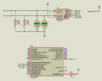
Hi guys I'm facing problem interfacing serial dac with picf2550. i tried simulation, it works but hardware is not working. Actually I'm trying to generate modefied sine and cos waves.

I think there might be something I'm doing wrong with configuration bits or may be SPI is different.
Need suggestion.

P.S: i tried the same code with a few changes with PIC18F452 its works. than why its not working with 2550???


here is code n schematic:
Code:
#include<htc.h>


//__CONFIG(1,PLLDIV4 & CPUDIV_OSC1_PLL2 & USBDIV_2 & IESO_OFF & FCMEN_OFF & FOSC_HSPLL_FOSC = INTOSC_EC);
__CONFIG(1,PLLDIV2  & IESO_OFF & FCMEN_OFF & FOSC_HS);
__CONFIG(2,VREGEN_OFF & BOR_OFF & BORV_0 & PWRT_ON & WDT_OFF);
__CONFIG(3, MCLRE_ON & PBADEN_OFF & LPT1OSC_OFF & CCP2MX_ON);
__CONFIG(4,DEBUG_ON & LVP_OFF & STVREN_OFF & XINST_OFF);


#define _XTAL_FREQ 8000000   
#define chip_sel RB3


void dac(unsigned int, unsigned int);


const unsigned int sine [28]={2048,2503,2936,3324,3648,3892,4044,4095,4044,3892,3648,3324,2936,2503,2048,1592,1159,771,447,203,51,0,51,203,447,771,1159,1592};	//works well modified sine wave


unsigned char count=0,new_sector=0, old_sector=0,i=0, j=7;	//14
unsigned int value=0,time=0;
unsigned long time_div=0;


void main(){
	 TRISB=5;                   
 	 PORTB=0;


	TRISC=0;
	PORTC=0;


	PORTA=0;
	TRISA=0;


	ADCON1=0x0f;		
	CMCON=0x07;


	GIE=1;
	PEIE=1;
	TMR2IP=1;
	TMR2IE=1;


	PR2=100;		//hv to adjust this value for exact frequency
	TMR2=0;


 	SSPSTAT=0xC0;              //Status Register SSPSTAT=11000000
 	SSPCON1=0x20;             //Enables serial port pins & set the SPI clock as clock = FOSC/4


	T2CON=0x04;
	while(1);


	}


void dac(unsigned int data, unsigned int dac_sel)
{
	
  	unsigned int lower_bits;
  	unsigned int upper_bits;  


  //first obtain the upper 8 bits
  	upper_bits = data/256;                          // obtain the upper 4 bits
  	upper_bits = (dac_sel) | upper_bits;         // append 48 to the above 4 bits for DACa o/p n 176 for DACb o/p


  //now obtain the lower 8 bits
  	lower_bits = 255 & data;                      // ANDing separates the lower 8 bits
  
  	chip_sel=0;
  	SSPBUF=upper_bits;                      // sending the upper 8 bits serially     
  	while(!SSPSTATbits.BF);                // wait until the upper 8 bits are sent
  	SSPBUF=lower_bits;                      // sending the lower 8 bits serially   
  	while(!SSPSTATbits.BF);                // wait until the lower 8 bits are sent
  	chip_sel=1;
}


void interrupt tc_int(){


	if(TMR2IE && TMR2IF){		


		dac(sine[i],48);
		dac(sine[j],176);
		i++;if(i>=28)i=0;		
		j++;if(j>=28)j=0;
		TMR2IF=0;
	
		
	}


}

Capture.PNG
 

Change config setting

Code:
DEBUG_ON

to

Code:
DEBUG_OFF

and compile the project for Release and not for Debug.
 

i need this on for debugging. I dont think so that the problem.
 

NEVER set the DEBUG option to anything! Just don't mention it at all.
Leave it to the IDE to set it according to whether you are doing a release or debug build.
Also you really should explain what "not working" actually means. What does work the way you want it to? What is it doing that it should not do?
Susan
 

Something in schematic seems like not matching the code; You defined the oscillator source being a crystal of 8MHz, but at the drawing there is nothing connected at the OSC1 pin.
 

I tried with release mode with debug off but getting nothing from dac. Clock, Data is coming from controller but nothing at the output of DAC except noise.

I set 8MHz Crystal in controller edit properties setting.

P.S: I tried the code with mickroc Pro for PIC with its own libraries its working. i think there is some problems in SPI.
any suggestion?
 

Zip and post your mikroC PRO PIC project and also the Proteus file. Write your own software SPI code for communicating with the DAC.
 

Thread #7 is great answer. If you want to go long time you would understand it. After understand it you will not need to ask any question regarding to SPI.
It is a small & easy to understand protocol & hardware connections.
1. MODE SELECT :- generally we use mode 1 & 3 but you would read MCP4922 datasheet. Witch mode it accept?
2. SERIAL CLOCK :- Set serial clock source configuration (From external or internal...).
3. CS set :- You can select chip with software or hardware configuration. If you have only one chip at port. You will not need to configure it. You can connect this pin to ground directly.
 

Thnx for your suggestions.

I'll try to write my own SPI routines and post the results.
 

You need to be a bit careful when talking about SPI "modes" and PIC MCUs in that there is no simple 1:1 match between the common "mode" values and the CHP, CKE and SMP.
Have a look at Page 25 in https://ww1.microchip.com/downloads/en/devicedoc/spi.pdf (for example - there are many other references).
By far the most reliable method is to look at the data sheet for the device you are talking to and then the data sheet/FRM section for the MCU and cross-check that you are not transitioning the SDO signal when the other device is trying to sample it; same for sampling the SDI signal.
Susan
 

thnx for informative help. I read almost every concerning data regarding SPI,:grin: I think now I know how to find a path to success. haha

I'll soon start to write routines than check with hardware and post the results.

Regards.
Maliks
 

I have done coding and hardware simulation, SPI is working now but the (DAC output) frequency of modified sine and cos wave is varying.
Suggestions.!!!!!

Here is the SPI.c
Code:
 unsigned char SSP1_Wait_IF(void) 
 { 
         while(!SSPIF); 
         SSPIF = 0; 
         return SSPBUF; 
 }

Here is SPI.h
Code:
#ifndef _SPI_H
#define _SPI_H

 // ---------------------------- 
 // MSSP1 SPI Port config 
 // ---------------------------- 
 #define    SPI1_CLK_TRIS    TRISBbits.RB1     
 //#define    SPI1_SDI_TRIS    TRISCbits.RB0 
 #define    SPI1_SDO_TRIS    TRISCbits.RC7 

 // INIT I/O for MSSP1 SPI bus 
// #define    INIT_SPI1_PORT()    {SPI1_CLK_TRIS=0; SPI1_SDO_TRIS=0; SPI1_SDI_TRIS=1;} 

 #define INIT_SPI1_PORT()	{SPI1_CLK_TRIS=0;SPI1_SDO_TRIS=0;}

// MSSP1 SPI Config and control 
 // ---------------------------- 
 #define    SPI1_CONFIG        0b00000000    // Master,  Clock = FOSC/4, MSSP Disabled 
 #define    SPI1_Enable()        (SSPCON1bits.SSPEN=1) 
 #define    SPI1_Disable()        (SSPCON1bits.SSPEN=0)
 
 // Init MSSP1 SPI bus 
 #define    SPI1_Init()        {SSPCON1=SPI1_CONFIG; SSPSTATbits.CKE=1; SSPSTATbits.SMP=0; PIR1bits.SSPIF=0;} //ckp=0. cke=1 mode 0, 0
 
 // ---------------------------- 
 // SPI1 TX/RX primitives 
 // ---------------------------- 
 // Wait transfer complete (pooling interrupt flag) 
 // return content of TX/RX Buffer after transfer complete (received data) 
 unsigned char SSP1_Wait_IF(void); 
 
 // Send a byte to the SPI1 bus 
 #define SPI1_SEND(DATA)        {SSPBUF = DATA; SSP1_Wait_IF();} 
 
 // Read a byte from the SPI1 bus (send dummy to generate clock) 
 #define    SPI1_RECEIVE(DATA)    {SSPBUF = 0; DATA = SSP1_Wait_IF();} 
 
 #endif

and here is main code

Code:
#include<htc.h>
#include "spi.h"


__CONFIG(1,PLLDIV2 & CPUDIV_OSC1_PLL2 & USBDIV_2 & IESO_OFF & FCMEN_OFF & FOSC_HSPLL_HS);
//__CONFIG(1,PLLDIV2  & IESO_OFF & FCMEN_OFF & FOSC_HS);
__CONFIG(2,VREGEN_OFF & BOR_ON & BORV_3 & PWRT_OFF & WDT_OFF & WDTPS_32768);
__CONFIG(3, MCLRE_ON & PBADEN_OFF & LPT1OSC_OFF & CCP2MX_ON);
__CONFIG(4,DEBUG_ON & LVP_OFF & STVREN_ON & XINST_OFF);
__CONFIG(5,CP0_OFF & CP1_OFF & CP2_OFF & CP3_OFF & CPB_OFF & CPD_OFF);
__CONFIG(6,WRT0_OFF & WRT1_OFF & WRT2_OFF & WRT3_OFF & WRTC_OFF & WRTB_OFF & WRTD_OFF);
__CONFIG(7,EBTR0_OFF & EBTR1_OFF & EBTR2_OFF & EBTR3_OFF & EBTRB_OFF);

#define _XTAL_FREQ 32000000   
#define chip_sel RB3

void dac(unsigned int, unsigned int);


const unsigned int sine [28]={2048,2503,2936,3324,3648,3892,4044,4095,4044,3892,3648,3324,2936,2503,2048,1592,1159,771,447,203,51,0,51,203,447,771,1159,1592};	//works well modified sine wave


unsigned char count=0,new_sector=0, old_sector=0,i=0, j=14;	//7
unsigned int value=0,time=0;
unsigned long time_div=0;


void main(){


	ADCON1=0x0f;		
	CMCON=0x07;

	GIE=1;
	PEIE=1;
	SSPIE=1;
	TMR2IP=1;
	TMR2IE=1;


	PR2=100;		//freq 595 hz this value is without any calculations
	TMR2=0;


	INIT_SPI1_PORT();		//init spi pins
 	SPI1_Init() ;			//init spi
	

	T2CON=0x7C;
	while(1){


	}
		
}

void dac(unsigned int data, unsigned int dac_sel)
{
	
  	unsigned int lower_bits;
  	unsigned int upper_bits;  
  

  //first obtain the upper 8 bits
  	upper_bits = data/256;                          // obtain the upper 4 bits
  	upper_bits = (dac_sel) | upper_bits;         // append 48 to the above 4 bits for DACa o/p n 176 for DACb o/p


  //now obtain the lower 8 bits
  	lower_bits = 255 & data;                      // ANDing separates the lower 8 bits
  	
	SPI1_Enable() ;
  	chip_sel=0;
	SPI1_SEND(upper_bits);
	SPI1_SEND(lower_bits);
  	chip_sel=1;
	SPI1_Disable();
}

void interrupt tc_int(){

	if(TMR2IE && TMR2IF){		
	
		dac(sine[i],48);
		dac(sine[j],176);
		i++;if(i>=28)i=0;		
		j++;if(j>=28)j=0;
		TMR2IF=0;

		
	}
	 
}
 

Hi,

I can´t see what´s your interrupt frequency.

Are you sure the time between two interrupts is less than the ISR needs (with all it´s overhead)?

Klaus
 

For a start NEVER set the "DEBUG" config setting to anything - just don;t mention it at all. The IDE will set this for you depending on whether you are doing a release or debug build.
I have tried to interpret your actual config and code and this is what I have come up with:
I'm guessing that you have a 8MHz crystal as you are using the PLL (which requires a 4MHz input) and the PLL Prescalar is "divide by 2".
The PLL outputs 96MHz which you then divide by 2 (the PLL postscalar) to give 48MHz.
The Timer2 uses Fosc/4 so its input frequency is 12MHz. The timer prescalar is 1:1, the post scalar is 1:16 and the PR2 value is 100. Therefore the timer will interrupt at 7500Hz or approximately once every 133 uSec.
You set the MSSP up as an SPI master with Fosc/4 or a 12MHz clock. That means that you will send 8 bits in 0.666uSec (for which you block the ISR). Given that you are sending 2 bytes and there will also be some overhead, I'm guessing that you will be taking at least 2uSec to actually send the values to the DAC.
While this would seem to be enough time, there is also a lot of overhead with the ISR and the other code that I simply cannot try to estimate.
Of course, if any of my guesses and assumptions are wrong then the above will also be incorrect (probably worse timing-wise).
A couple of comments: personally I really hate putting all of that code into #define's and then treating them as functions, especially when the defines use #defines inside them: it is far too easy to get something wrong and it is very hard to understand and debug the resulting code.
There is no need to enable and disable the MSSP each time you want to use it. Just enable it at the start and leave it enabled.
You are using RB3 as the chip select - you should be using the LAT register to control this pin to avoid any RMW issues, especially as some of the other PORTB pins are used for the SPI.
My preferred way to approach this would be to set the timer for whatever frequency you want to update and then poll for the IF begin set in the main loop - don't use interrupts (why complicate this unnecessarily). The timer will automatically reset itself and start counting for the next period. When the main loop sees the IF bit set, it can clear it and then execute the code to write the value to the DAC. This avoids calling any blocking functions (such as your SPI code) in an ISR. As long as you can execute the code in less time than the next timeout period, then the frequency of updates should be fixed.
Susan
 
  • Like
Reactions: KlausST

    KlausST

    Points: 2
    Helpful Answer Positive Rating
Here I am attaching the .hex file and Proteus 8.3 SP2 format file. Test the Simulation and also test it in hardware.

- - - Updated - - -

Fixed a small bug. Try Rev1 file.

- - - Updated - - -

Try attached Proteus Circuit with attached Rev2 .hex file.
 

Attachments

  • DAC MCP4922_PIC18F2550_8MHz.rar
    15.3 KB · Views: 99
  • DAC MCP4922.png
    DAC MCP4922.png
    33.8 KB · Views: 374
  • DAC MCP4922_PIC18F2550-8MHz_Rev1.rar
    700 bytes · Views: 92
  • DAC MCP4922_PIC18F2550_8MHz_Rev2.rar
    16 KB · Views: 98
Last edited by a moderator:

Edit:

Ok. Here you go. I am attaching the mikroC PRO PIC project I made. You can't reduce the delays more. It took just 15 minutes to write this code.
 

Attachments

  • DAC MCP4922 PIC18F2550 8 MHz mikroC PRO PIC.rar
    21.3 KB · Views: 81

Ok. Here you go. I am attaching the mikroC PRO PIC project I made. You can't reduce the delays more.
You are using bit-banging SPI instead of the PIC hardware SPI. It's hardly possible to achieve a similar speed this way.

I don't see how the designs in post #16 and #17 can be helpful.
 

Here you go. Code using hardware SPI function. I am using mikroC PRO PIC hardware SPI1 library.

Edit: Here is another code. It uses Hardware SPI1_Init_Advanced() function.


Code C - [expand]
1
2
3
4
5
6
7
8
9
10
11
12
13
14
15
16
17
18
19
20
21
22
23
24
25
26
27
28
29
30
31
32
33
34
35
36
37
38
39
40
41
42
43
44
45
46
47
48
49
50
51
52
53
54
55
56
57
58
59
60
61
62
63
64
65
66
67
68
69
70
71
72
73
74
75
76
77
78
79
80
81
82
83
84
85
86
87
88
89
90
91
92
93
94
95
96
97
98
99
100
101
102
103
104
105
106
107
108
109
110
111
112
113
114
115
116
117
118
119
120
121
122
sbit MCP4922_CS   at LATB3_bit;
sbit MCP4922_LDAC at LATB2_bit;
sbit MCP4922_SHDN at LATB4_bit;
 
sbit MCP4922_CS_Direction   at TRISB3_bit;
sbit MCP4922_LDAC_Direction at TRISB2_bit;
sbit MCP4922_SHDN_Direction at TRISB4_bit;
 
#define WRITE_TO_DAC_A 0
#define WRITE_TO_DAC_B 1
 
#define BUFFERED   1
#define UNBUFFERED 0
 
#define GAIN_1x 1
#define GAIN_2x 0
 
#define ACTIVE_MODE 1
#define SHUTDOWN    0
 
void MCP4922_Init() {
    MCP4922_CS_Direction    = 0;
    MCP4922_LDAC_Direction  = 0;
    MCP4922_SHDN_Direction  = 0;
 
    MCP4922_CS = 1;
    MCP4922_LDAC = 1;
    MCP4922_SHDN = 1;
    
    SPI1_Init_Advanced(_SPI_MASTER_OSC_DIV4, _SPI_DATA_SAMPLE_MIDDLE, _SPI_CLK_IDLE_LOW, _SPI_LOW_2_HIGH);
}
 
void MCP_Send(unsigned int ab, unsigned int buf, unsigned int ga, unsigned int mode, unsigned int value) {
    char i = 0;
    unsigned int mask = 0x8000;
    
    value = value & 0x0FFF;
    value |= (ab << 15);
    value |= (buf << 14);
    value |= (ga << 13);
    value |= (mode << 12);
    
    _asm {
       nop;
       nop;
    }
    
    MCP4922_LDAC = 1;
    
    _asm {
       nop;
       nop;
    }
    
    MCP4922_CS = 0;
    
    _asm {
       nop;
       nop;
    }
    
    SPI1_Write((value & 0xFF00) >> 8);
    SPI1_Write(value & 0x00FF);
 
    _asm {
       nop;
    }
    
    MCP4922_CS = 1;
    
    _asm {
       nop;
       nop;
    }
    
    MCP4922_LDAC = 0;
    
    _asm {
       nop;
       nop;
    }
    
    MCP4922_LDAC = 1;
}
 
signed int j = 0;
 
void main() {
 
    ADCON1 = 0x0F;
 
    TRISA = 0xC0;
    TRISB = 0x00;
    TRISC = 0x00;
 
    PORTA = 0x00;
    PORTB = 0x00;
    PORTC = 0x00;
 
    LATA = 0x00;
    LATB = 0x00;
    LATC = 0x00;
 
    MCP4922_Init();
    
    while(1) {
 
        for(j = 0; j < 4096; j++) {
             MCP_Send(WRITE_TO_DAC_A, UNBUFFERED, GAIN_2x, ACTIVE_MODE, j);
             Delay_ms(1);
        }
        
        Delay_ms(2000);
        
        for(j = 4095; j >= 0; j--) {
             MCP_Send(WRITE_TO_DAC_A, UNBUFFERED, GAIN_2x, ACTIVE_MODE, j);
             Delay_ms(1);
        }
        
        Delay_ms(2000);
    }
}


Attachments

  • DAC MCP4922 PIC18F2550 8 MHz mikroC PRO PIC HW SPI.rar
    21.4 KB · Views: 80
Last edited:

Thnx pic.programmer. I already tested Mikro C successfully as I mentioned it in post no.6, but for debugging I required MPLAB + Hitech (as I'm using PICKIT 3).

I found the frequency fluctuation problem, hardware design error, and everything is working fine now.
Again thnx.

Regargs!!
Maliks
 

Status
Not open for further replies.

Similar threads

Part and Inventory Search

Welcome to EDABoard.com

Sponsor

Back
Top