Continue to Site

Welcome to EDAboard.com

Welcome to our site! EDAboard.com is an international Electronics Discussion Forum focused on EDA software, circuits, schematics, books, theory, papers, asic, pld, 8051, DSP, Network, RF, Analog Design, PCB, Service Manuals... and a whole lot more! To participate you need to register. Registration is free. Click here to register now.

[SOLVED] Measuring current without using shunt resistance

Status
Not open for further replies.

farrukhtalib

Junior Member level 3
Joined
Jul 16, 2010
Messages
25
Helped
0
Reputation
0
Reaction score
0
Trophy points
1,281
Activity points
1,487
Hi All
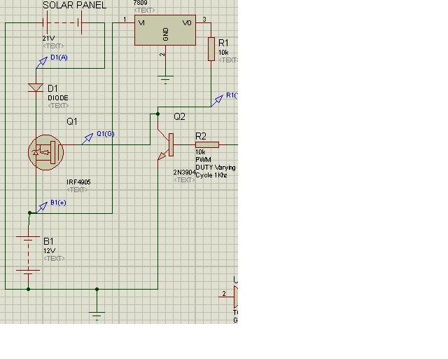
If some one may guide me that how may I able to measure current in the following circuit using HEXFET instead of shunt resistane.

6049649300_1442924352.jpg
 

voltage of drain-source of your hexfet will be good option...
V(Rds-on) is good shunt resistor for measure current....
 

It is not straight forward to measure the current accurately without a shunt resistor. One solution is to measure the voltage drop across the diode D1. To do that, you need to know (or characterize) the diode voltage vs. current. This current measurement may not be very accurate, but good enough to give indication of over-current conditions. You can use the same technique by measuring the voltage drop across the FET Q1. Again you need to know the Rds-ON vs current characteristic of the FET.

I see that you are pulse charging the battery B1. What kind of battery is that? Lead-acid? Pulse charging is somewhat dangerous. You need to be careful. See this page if you want to learn more about battery charging.
 
i've done oodles of pulse charging of batteires. 1000V spike, miliamp current (ideally zero amps). it was in a few microseconds of pulse time (collapsing field of an inductor provided the spike to charge battery). it wasn't so dangerous. sometimes the battery would boil (off gassing) so you just backed off a bit. i did this for YEARS, it is by far the best way to energize a battery.

as for your measuring of current, there are actually mosfets that have built in a current sense. perhaps you might use that instead? i think they are called Sensefets ?

ya, here is one. i grab datasheet at random: https://www.onsemi.com/PowerSolutions/product.do?id=NTMFS4854NS
 
If you put an inductor in series with the battery, then every time the PWM switches off, you will get a voltage spike across it v = l X di/dt, as the Dt will not change or the l, the voltage will be proportionate to the current being switched off. So you could feed this into a diode peak detector and measure the voltage. Or use a transformer to step the spike up and DC isolate it.
Frank
 
If the small voltage drop of a shunt resistor matters for your application, you would get rid of the rectifier diode and replace it by a "lossless" MOSFET circuit first.

Current measurement with means of a MOSFET transistor switch is possible, but relative inaccurate due to type variations and temperature dependency od Rdson. It requires to sample and hold the voltage in on-state, in other words a complex analog circuit.

The circuit in post #1 isn't working due to wrong gate voltage. The MOSFET turns on independent of the pwm signal at higher solar panel voltage. Also the maximum Vgs rating is most likely exceeded.
 

OK I cannot understand why MOSFET will be on independent of PWM?
will you correct my circuit?
 

To switch off, the gate voltage must swing to Vin, e.g. 21V, but it's limited to 9V.

Could be modified like below

korr.jpg
 

But according to data sheet V GS may not exceed than +/- 20 so in that case it will b come more than 20 Volts? and what is the purpose of schottky diode ? is it sort of virtual ground arrangement ?
 

Difficulties to calculate Vgs? Source is at the positive solar panel terminal, Vgs is relative to source.
 

To measure hi-side current a hall effect device is a pretty good way to do it, Raztec make a few...
 

Hi
Dear sir in your modified circuit u used a voltage divider to pull voltage down according to the spacified VGS ratings. It is OK when there is a positive pulse at the base of the switching transistor (Q2) but when there is negative pulse there then the gate voltage will become +21 which is more than absolute VGS rating according to the data sheet of IRF 4905. Will it destroy the mosfet or not?
 

How to to calculate P-Channel FET Gate voltage to off it at high side in 48V rail ?

Hi
I am using a p Chanel mosfet irf 4905 for my application the voltage rail is not constant (SOLAR PANEL) 13 to 48 connected to source. The VGS is +- 20. How may i calculate the gate voltage which may turn MOSFET fully off
 

Re: How to to calculate P-Channel FET Gate voltage to off it at high side in 48V rai

Very simple. Vgs = 0. Means your gate driver has to apply a voltage relative to source terminal. As suggested in your previous thread.
 

Re: How to to calculate P-Channel FET Gate voltage to off it at high side in 48V rai

your communications skills are excellent but am still confused that if I am using 48 volts at source as V in then may i step it down to achieve safe range of V gs i.e/ below 20 or may i subtract 48 volts from vgs In this case the voltage on gate will cross the threshold boundary and PMOS will be destroyed?
 

How to turn Off PMOS when Voltage at source is higer than Max Vgs

Hi All,
Please have a look at the attached fig and let me know where I am wrong I did my best but am unable to turn off PMOS. In this case the V in is 39 volts and max Vgs of PMOS is +- 20

https://obrazki.elektroda.pl/3053043600_1443788898.jpg
 

Re: How to turn Off PMOS when Voltage at source is higer than Max Vgs

Hi,

Vgs means: Voltage between Gate and Source. No absolute voltage to GND.

In your picture: just disconnect R2 to turn OFF the MOSFET.

Klaus
 

Re: How to turn Off PMOS when Voltage at source is higer than Max Vgs

ya but in this case the voltage on gate will be around 39 which will destroy the PMOS
 

nope.

To measure Vgs, connect the instrument this way

vgs1.JPG
 

So what is the difference between ur and mine connection
I am not too good in electronics pls treat me as less experienced man and pls clear my concept.
The data sheet says u cannot apply more than +- 20 volts at the gate. Now the source voltage is high than that absolute value now what to do?. Please reply in tutorial mood
 

Status
Not open for further replies.

Similar threads

Part and Inventory Search

Welcome to EDABoard.com

Sponsor

Back
Top