Continue to Site

Welcome to EDAboard.com

Welcome to our site! EDAboard.com is an international Electronics Discussion Forum focused on EDA software, circuits, schematics, books, theory, papers, asic, pld, 8051, DSP, Network, RF, Analog Design, PCB, Service Manuals... and a whole lot more! To participate you need to register. Registration is free. Click here to register now.

Prevent audio leaking

Status
Not open for further replies.

zentos

Member level 1
Joined
Apr 7, 2014
Messages
33
Helped
0
Reputation
0
Reaction score
0
Trophy points
6
Activity points
278
Hi There,

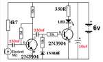
I'm working for a design which light LED when its detect audio input to the circuit from a mobile phone. There are few same design doing the same thing. Detect audio and light LED is fine but the problem is Audio sensor circuit leaking audio to power source. I have check with Audio tracer. I need help to prevent audio leakage to power source. Please kind to help someone on this matter. Appreciate.

Note : If can amplify signal to very sensor level really good.

SOUND-TRIGGERED-LED.gif


Sorry it has to corrected as More sensor to more sensitive? Any one please give me any advise on this matter..
 

The audio draws power from the DC source.
The DC source is not a true voltage source and has ESR or effective series reistance.

Thus injected audio can reduce supply voltage when current increases.

We call this % load regulation, the ratio of change in source DC voltage with full load signal.
 

more sensitive?

To make the detector more sensitive, you'll need to adjust the bias levels to the transistors.

In other words, where the schematic has a 10k resistor, substitute a potentiometer, say 20 or 50 k.

It should be possible to adjust settings so that the led lights when soft sound reaches the mic. And when there is no sound, the circuit should draw very little power.
 

The problem is the 10uF cap is 100x bigger than the 100nF cap and it tales a long duration to get enough pulses to charge it up to a few volts.. Changes LED driver to a Darlington configuration and use an active peak detector. or similar.
 

Thanks for the reply. But I couldn't find any solution for the leaking audio to power source. Finally decide to supply individual power supply (Rechargeable batteries) to each audio sensor circuit. Ohh.. God why this audio electronics become more difficult to me...:-(

- - - Updated - - -

The problem is the 10uF cap is 100x bigger than the 100nF cap and it tales a long duration to get enough pulses to charge it up to a few volts.. Changes LED driver to a Darlington configuration and use an active peak detector. or similar.

I didn't used that cap (10uf) cos don't need delay but it's working good. Thanks.
 

Since you did not use the 10uf capacitor then the LED blinks for every half-cycle of the audio so with continuous sound it is turned on for only half the time and appears dimmed.
The LED blinks with every half cycle of audio but the blinking for most frequencies is much faster than your vision can see it so again most sounds produced dimmed light.

You removed the 10uF capacitor then you also do not need the diode in series with the signal that reduced sensitivity.

The circuit had the base-emitter diode of the transistor charging the coupling capacitor but nothing discharging it so again the sensistivity was reduced.
I put the diode in series with the 10k resistor to ground so that its polarity is the opposite to the polarity of the base-emitter diode and it discharges the coupling capacitor on every half cycle for good sensitivity.

I increased the value of the 100nf capacitors to 330nF so that they pass low audio frequencies and added a 10uF important supply bypass capacitor.
 

Attachments

  • changed sound trigger.png
    changed sound trigger.png
    10.1 KB · Views: 102

This may improve sensitivity to audio for you.

Use Electret Mic and 10k or 4k7 for mic pullup bias..
Shown for 5V with White LED (3V) for Red use 82 Ohm (2V)

In this design I Used emitter follower to act as current buffer and rectifier. and Darlington to drive LED , to stretch decay time on Cap. you can increase Cap more but not too much.


In this design I Used emitter follower to act as current buffer and rectifier.
It does not have an emitter follower. Instead it has a PNP common emitter class-C amplifier that needs a signal level of about 0.5V to 0.6V peak to turn it on.
The electret mic has an output level of only about 10mV so the transistor will NEVER turn on unless there is a nuclear bomb blast nearby.
 

It does not have an emitter follower. Instead it has a PNP common emitter class-C amplifier that needs a signal level of about 0.5V to 0.6V peak to turn it on.
The electret mic has an output level of only about 10mV so the transistor will NEVER turn on unless there is a nuclear bomb blast nearby.

my dog died,
Audioguru has not made any friends yet.
corrected below

7093005100_1441313590.jpg


An Op Amp circuit can do much better than this, but FWIW ( for what it's worth.... )
Base Resistor ratio is sensitive to ON/OFF.
 

my dog died, corrected below

7093005100_1441313590.jpg


An Op Amp circuit can do much better than this, but FWIW ( for what it's worth.... )
Base Resistor ratio is sensitive to ON/OFF.


Thank you very much sir. I'll make this one and will post the result.
BTW,
**Is that resistor 10 M or 10 K from the input (Mic input) ?
** Can I use BC 547 (PNP) and BC557 (NPN) for the transistors?
** Is there any option to adjust sensitive?

If you can attach clear image really appreciate.
 

Since you did not use the 10uf capacitor then the LED blinks for every half-cycle of the audio so with continuous sound it is turned on for only half the time and appears dimmed.
The LED blinks with every half cycle of audio but the blinking for most frequencies is much faster than your vision can see it so again most sounds produced dimmed light.

You removed the 10uF capacitor then you also do not need the diode in series with the signal that reduced sensitivity.

The circuit had the base-emitter diode of the transistor charging the coupling capacitor but nothing discharging it so again the sensistivity was reduced.
I put the diode in series with the 10k resistor to ground so that its polarity is the opposite to the polarity of the base-emitter diode and it discharges the coupling capacitor on every half cycle for good sensitivity.

I increased the value of the 100nf capacitors to 330nF so that they pass low audio frequencies and added a 10uF important supply bypass capacitor.

Thank you very much sir. Tomorrow I'll make this one too and reply. Appreciate.
 

Thank you very much sir. I'll make this one and will post the result.
BTW,
**Is that resistor 10 M or 10 K from the input (Mic input) ?
Ignore Ant/10M , I used 10K instead of 4.7K

** Can I use BC 547 (PNP) and BC557 (NPN) for the transistors?
YES
** Is there any option to adjust sensitive?

If you can attach clear image really appreciate.

Replace 1M/6.5M with 1M trimPOT & ~6M fixed but limit range with a fixed R to adjust Vbe bias and load.
 

Thank you very much sir. Tomorrow I'll make this one too and reply. Appreciate.

I have build the given one. But sensitive bit low when low audio input. I did change bit and now sensitive seems fine. Thank you.

changed sound trigger11.png

- - - Updated - - -

Replace 1M/6.5M with 1M trimPOT & ~6M fixed but limit range with a fixed R to adjust Vbe bias and load.

At the moment some of this resistors doesn't have with me. Once I find ,will make this too. Thank you sir.
 

Status
Not open for further replies.

Similar threads

Part and Inventory Search

Welcome to EDABoard.com

Sponsor

Back
Top