Continue to Site

Welcome to EDAboard.com

Welcome to our site! EDAboard.com is an international Electronics Discussion Forum focused on EDA software, circuits, schematics, books, theory, papers, asic, pld, 8051, DSP, Network, RF, Analog Design, PCB, Service Manuals... and a whole lot more! To participate you need to register. Registration is free. Click here to register now.

3rd overtone crystal oscillator not wirking at right frequency

Status
Not open for further replies.

visions_of_eden

Newbie level 5
Joined
Jun 8, 2011
Messages
9
Helped
1
Reputation
2
Reaction score
1
Trophy points
1,283
Activity points
1,369
Hi,

i have a problem with a simple 30.875Mhz (garage opener) crystal oscillator .

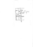
The problem is that the frequency it generates is not the expected one . On the attached schematics , if i measure the frequency using a frequency counter on "A" point i get 30.876Mhz which is correct , but on the other side of the 27pF capacitor at "B" only get 20.606Mhz .

My crystal is a 3rd overtone crystal , is it possible that it's oscillating at 2nd overtone frequency ? Why do i get a lower frequency on the capacitor ?

The output of my oscillator will be fed into a ASK modulator , so the capacitor is only needed to cut DC offset from next modulator stage . Why does it cut the frequency ?
Maybe the oscillator has not a good stability ? What sould i check ?

I don't have expericence with oscillators , so sorry if my questions looks stupid .

Thansk in advance .

Nicola .
 

Attachments

  • Oscillator.JPG
    Oscillator.JPG
    291.3 KB · Views: 175

Although it may be the case, that you are actually forcing 2nd overtone oscillations by forming an unwanted resonant circuit with 27 pF capacitor and additional parasitic capacitances, I won't blindly believe the frequency counter and check with an oscilloscope. Normally overtone crystals have geometries that prefer the wanted frequency. Oscillations on the fundamental are however observed in some high gain circuits.
 

Checked with oscilloscope and got strange results .

Frequency at "A" point is fundamental frequency , 10.3Mhz .

Oscillator does not oscillate at 2nd overtone nor at 3rd , but at fundamental frequency .

The strange thing is that if i connect both oscilloscope probe and frequency counter probe to the circuit at point "A" , the frequency of the signal change to 30,875 Mhz .

Even if i touch the base of the transistor the frequency shifts to 30,875Mhz .

I don't know what to think .

Not having experience with this kind of circuits it's hard for me to find a solution .

If anybody has in idea of what's going on and what to try to fix it whould help me very much .
 

Why do you think a 30 MHz xtal is third overtone? Not impossible but unusual. No such thing as oscillating at 2nd overtone.

Try putting a 30 to 40 pF between base and emitter of bjt. Short out 1 uH and look at emitter for output with small coupling cap. This configure would be parallel fundament mode If it is a third overtone crystal that circuit will not work for it.
 

Why do you think a 30 MHz xtal is third overtone? Not impossible but unusual.

I will try , but i'm sure it's a 3rd overtone crystal since i bought it here :

IQD | Semiconductors | Frequency Control | Crystals | Crystals |LFXTAL018471

and from datasheet it's specified that this crystal works on 3rd overtone .

No such thing as oscillating at 2nd overtone.

The crystal does not oscillates on 2nd overtone . I got a wrong result from the frequency meter.
Measuring frequency with the oscilloscope showed that the frequency it works on is 10.3Mhz .
I tried to add a capacitor in parallel with 1uH inductor and tune the LC tank to desired frequency but this does not work too .
 
You should refer to an oscillator circuit dedicated to overtone crystals. They usually have a tuned circuit directly conncted to the crystal.

P.S.: In your circuit, the tuned circuit is only losely coupled to the crystal (through Ccb). So it won't supress unwanted oscillations.
 
Last edited:

That was my thought as well - it isn't an overtone oscillator circuit. Even as a multiplier the collector load should be tuned, which it isn't.

Keith
 

Even as a multiplier the collector load should be tuned, which it isn't.

Keith

Interesting . What kind of modifications should i do to make it act as a multiplier ?
Maybe the original circuit was supposed to be a multiplier and not an overtone oscillator .

I took the circuit from a real garage door opener that i use in my house .
I can confirm that the overtone crystal works in the original design since i replaced one from a broken remote control .

I will also try with another circuit design , but i would like to figure out why the original circuit works while mine do not .
 

but i would like to figure out why the original circuit works while mine do not .
Maybe it's a matter of layout and connected load. Because the cicrcuit isn't a stable overtone oscillator, many parameters can play a role.
 

Maybe it's a matter of layout and connected load. Because the cicrcuit isn't a stable overtone oscillator, many parameters can play a role.

Layout don't seems to be critical since on 2 different remote controls implementing this same circuit layout change , maybe the load attached to the collector is the key .

While i was making some measures i noticed that with the frequency counter probe connected on collector , the output frequecy shifts to the correct one (30.875Mhz) .

Maybe the frequency meter act as a load to the oscillator .

Tomorrow i will post the full schematic of the remote control , so you could see what is the load connected to the oscillator .
However, to anticipate it , at point "A" , there's a capacitor that goes to the base of another BJT (2N2389A) . Between the base end the emitter there's only a 22uH inductor that pulls the base to ground . On the collector there's the primary of a transformer coil that act as antenna . The secondary is a tuned circuit that oscillates at 30.875Mhz .
 

Here's the full schematic .
 

Attachments

  • Oscillator_2.JPG
    Oscillator_2.JPG
    471.6 KB · Views: 143

It still doesn't look right to me. There is an inductor shorting out the 2N2369A base-emitter, for example.

I still don't see an obvious tuned circuit although 1uH and 27pF would resonate at the right sort of frequency so it could be that (but with different connections to the transistor).

You will certainly affect things by probing the circuit. Try using a simple loop of wire held over the circuit and connected to the oscilloscope.

Keith.
 

There is an inductor shorting out the 2N2369A base-emitter, for example.
It's a very simple class C output stage. A sufficient drive level is required to get any output, of course.

Generally, if it's the real product circuit, I believe that it works for the manufacturer. As stated, it's not a generic overtone oscillator circuit. Do you know for sure, if the original product uses an overtone crystal?
 

I am not sure it is an overtone crystal. The link to the RS catalogue says it is but the manufacturer's part number given by RS doesn't exist in IQD's catalogue and neither does the frequency. Also, the picture at the bottom of the RS page says "Fundamental resonance mode". As they do AT fundamental cut up to 40MHz it would be strange to go for a 3rd harmonic at 30MHz.

Keith.
 

Do you know for sure, if the original product uses an overtone crystal?

No , i don't know since on the original crystal there's only written 30.875Mhz , there's not a code to identify the crystal .

What i know for sure is that if you change the original crystal with the one i bought from RS the original opener still works . I had to replace the crystal from one of my remotes since one pin was broken, and i replaced it with this one and the remote still works .

About measuring the signals in the circuit , if i measure on the orignal remote , none of the parameters is altered , at output of oscillator there's a clean 30.875Mhz 2Vpp waveform , and on the antenna coil you can see the modulated ASK signal .

Don't know what to think .
 

I am not sure it is an overtone crystal....As they do AT fundamental cut up to 40MHz it would be strange to go for a 3rd harmonic at 30MHz.
If you check the 2000 c-mag catalog for the HC49/4H size, you'll notice, that 25 -40 MHz is offered both as fundamental and 3rd overtone type, but the ppm numbers are better for overtone. It's basically the same with present IQD products. So it's understandable, why a radio devive may use an overtone crystal, while processor crystals are mostly of the fundamental type. The fundamental frequency range has been apparently extended for recent SMD devices.

You'll always find some wrong data in catalog distributor product pages, but as the original poster was able to operate the crystal at 10.3 MHz, a 3rd overtone type should be assumed. And because it seems to work in the original circuit, it's not unlikely, that the latter has been designed for an overtone crystal. It's no problem to imagine that it can work and I assume, most RF engineers will be able to reproduce it's operation if required to. But they would mostly prefer a more stable overtone oscillator circuit.
 

Attached is a schematic for a 3rd overtone oscillator.

Warp coil is dependent on xtal parameters, probably about 2-2.5 uH for a 38 MHz 3rd overtone xtal.

A guess at a third overtone 38 Mhz crystal would be Cm about 3 fF, Lm about 5.85 mH, Rs about 20 ohms, Co about 6 pF. Oscillator loading capacitance is about 15 pF. Warp coil should pull about -20 ppm (-760 Hz) from Fs of crystal. You can figure warp coil with these parameters.

1K resistor across crystal prevents fundamental parallel mode oscillation. Crystal operates in series resonance mode. If there is a problem with oscillator running series mode at fundamental freq put a 10-15 uH choke in series with emitter resistor and bypass 2.2k resistor with a 1000 pF cap. That will kill loop gain at fundamental.

Output can be picked off emitter but care must be taken not to load it too much.

A low L, high C resonant tank can be put in collector to pick off harmonic of oscillator. Be aware any reactance or resistance put in collector path will reduce loop gain of oscillator. A low value resistor (100 ohms) in collector feeding a buffer/amp is okay.
 

Attachments

  • 3rd Overtone Osc.pdf
    164.2 KB · Views: 123
Last edited:

Status
Not open for further replies.

Similar threads

Part and Inventory Search

Welcome to EDABoard.com

Sponsor

Back
Top