Continue to Site

Welcome to EDAboard.com

Welcome to our site! EDAboard.com is an international Electronics Discussion Forum focused on EDA software, circuits, schematics, books, theory, papers, asic, pld, 8051, DSP, Network, RF, Analog Design, PCB, Service Manuals... and a whole lot more! To participate you need to register. Registration is free. Click here to register now.

Schematic Level and Block level implementation of Divide by 3 circuit.

Status
Not open for further replies.

shaikhsarfraz

Full Member level 5
Joined
Aug 8, 2006
Messages
285
Helped
25
Reputation
50
Reaction score
6
Trophy points
1,298
Activity points
2,961
Hi,
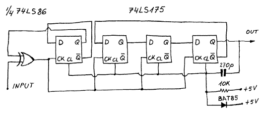
Can any body forward me the Schematic Level or Block level implementation of Divide - by - 3 circuit.

I need this block for the design of Frequency Synthesiszer.

Regards
Shaikh Sarfraz
 

Re: Divide by 3 Circuit

try this


this is working::::

**broken link removed**
 

Re: Divide by 3 Circuit

I am not able to view the site.

Can you send it through an attachment in EDA Board.

Its urgent

Thanks and Regards

Sarfraz
 

Re: Divide by 3 Circuit

I think it will be easier and judicial to implement a digital logic using flip flops rather then using analog blocks.

Any inputs from anybody ?

Regards
Sarfraz
 

Re: Divide by 3 Circuit

shaikhsarfraz said:
I think it will be easier and judicial to implement a digital logic using flip flops rather then using analog blocks.
Yes.

However, you've posted to the Analog Circuit Design and none of your previous posts said "digital". You'll get a better and quicker answer in the digital section of the EDAboard.
 

Divide by 3 Circuit

shaikhsarfraz
you can design divide3 using 2 flip-flops.
You deed at least 3 flip-flops if you want to 50%duty cycle.
 

Re: Divide by 3 Circuit

I am designing a frequency systhesizer.
This block has a divide by 3 (frequency divider) block.

I need a circuit with 50 % duty cycle.

Currently I am desiginig the other blocks.
So if some body can direclty give me some inputs on this issue it will be beneficial for me, as it will reduce the time for the project.

regards
sarfraz
 

Re: Divide by 3 Circuit

You can try CD4017 to make a divide by 3 counter, and then use CD4013 to make the pulse 50% duty.

nguyennam
 

Re: Divide by 3 Circuit

hi Shaikhsarfraz,

This should work . . .

37_1171123847.GIF


According to my simulator. :D

4_1171077237.JPG


on1aag.
 
Re: Divide by 3 Circuit

on1aag..

Did u designed it or copied from certain place else?
if the first, how could u? From FSM or what?

Regards,
Ahmad,
 

Re: Divide by 3 Circuit

this method use the control logic on clock path. I think it is not good for ASIC design. Is it there any other method to avoid logic on clock path?

thanks
 

Re: Divide by 3 Circuit

maybe you can try this. I used it for divide by 3 and worked pretty well
 

Re: Divide by 3 Circuit

u can use crystal oscillator wid a harmonic generator (as found in communication transmitters)
 

Re: Divide by 3 Circuit

bageduke said:
maybe you can try this. I used it for divide by 3 and worked pretty well

may i ask what's the frequency range it works at ? and how much current it draws.

i also used this architecture to realize a divider by 3, passed full corner simulation in a 0.18um CMOS process. but the current consumption is 6~10mA (it changes due to reference current is generated by internal resistor ) which is not acceptable。

so i am considering to change a method to realize divide by 3, first by 1.5, then by 2.
but not done yet, any idea?
 

Status
Not open for further replies.

Similar threads

Part and Inventory Search

Welcome to EDABoard.com

Sponsor

Back
Top