T
treez
Guest
Hello,
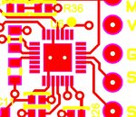
Our PCB assembler have told us that they are getting difficulties with soldering the PIC16F18856 [28 pin UQFN (4x4) ] on our board. They have actually asked us to make the copper pads smaller so that a solder resist bridge can be layed down between the pads. However, we are already using the microchip recommended footprint. (page 657 of datasheet)
Anyway, we are also getting problems with the lamp product that the micro is in. We configure the micro at production time so it knows what maximum dimming level to be at etc. Problem is, sometimes, (say in 5% of cases), the lamp doesn’t actually come back on after its startup routine. (the startup routine involves, whenever the lamp is switched on, the lamp comes on for 1 second, then dims down for 1 second, then goes off, then comes back on again, -just so’s we can see that the micro is compus mentus)….however, in say 10% of cases, the lamp doesn’t come back on after being configured.
We suspect this is due to dry joints in the micro pads. –eg the micro pin that connects to the light sensor may be dry and it may be seeing noise and think its light when its actually dark. Or the pin that connects to the temp sensor may have similar issues and think its too hot to turn the lamp back on etc etc.
Do you have any tips on ensuring no dry joints with this kind of footprint? Our footprint is exactly as on page 657 of the datasheet, but the assemblers want the pads trimmed back so solder resist can go between the pads……we currently have a 0.1mm solder resist bridge between each pad on the gerbers , but its so thin that the PCB manufacturer can’t produce it, and so we have no solder resist between the pads…the PCB assembler is complaining about this and reporting many failed boards to us.
PIC16F18856 datasheet
https://www.microchip.com/wwwproducts/en/PIC16F18856
(page 657 shows footprint of 28 pin UQFN)
We are also wondering about buying a cheap reflow oven so we can remove and resolder the micro ourselves so as to try and repair potential dry joints. Do you know of a cheap reflow oven.?
(The boards are 10cm by 8cm and 4 layer, components and leds only on top.)