sherif96
Member level 4
Butterworth transfer function transformation to tow thomas gm c
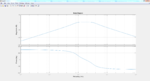
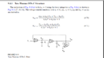
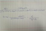
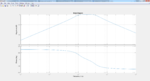
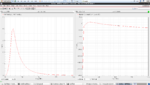
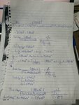
I have derived a 6th order butterworth bandpass filter transfer function with center frequency of 2 MHz and two cutoff frequencies at 1MHz and 3MHz, I am now trying to implement the filter using tow thomas gm c architecture, my transfer function and the bode plot of this transfer function are attached, I am trying to implement the attached tow thomas circuit also using Vo2 and Vi2 as they are the ones that could correspond to my transfer function with 3 cascaded stages to reach the 6th order, however I do not know what I am doing wrong in the transformation, I am comparing each 2nd order bracket from my transfer function and part of the gain multiplied by s with their corresponding coefficients in the tow thomas transfer function -assuming equal 500f capacitance- I get values for the transconductance which are incredibly wrong and their simulation are terribly wrong. I cannot understand what I did wrong in the transformation but it seems there is something I am missing.
I have derived a 6th order butterworth bandpass filter transfer function with center frequency of 2 MHz and two cutoff frequencies at 1MHz and 3MHz, I am now trying to implement the filter using tow thomas gm c architecture, my transfer function and the bode plot of this transfer function are attached, I am trying to implement the attached tow thomas circuit also using Vo2 and Vi2 as they are the ones that could correspond to my transfer function with 3 cascaded stages to reach the 6th order, however I do not know what I am doing wrong in the transformation, I am comparing each 2nd order bracket from my transfer function and part of the gain multiplied by s with their corresponding coefficients in the tow thomas transfer function -assuming equal 500f capacitance- I get values for the transconductance which are incredibly wrong and their simulation are terribly wrong. I cannot understand what I did wrong in the transformation but it seems there is something I am missing.