Continue to Site

Welcome to EDAboard.com

Welcome to our site! EDAboard.com is an international Electronics Discussion Forum focused on EDA software, circuits, schematics, books, theory, papers, asic, pld, 8051, DSP, Network, RF, Analog Design, PCB, Service Manuals... and a whole lot more! To participate you need to register. Registration is free. Click here to register now.

[SOLVED] Butterworth transfer function transformation to tow-thomas-gm c

Status
Not open for further replies.
Re: Butterworth transfer function transformation to tow thomas gm c

I was aware that the post #15 transfer function has an incorrect upper cut-off frequency of 4 MHz. Corrected below.

View attachment 145280

The appended Excel spreadsheet is calculating the gm-c parameters, optionally with gain correction for the 2nd and 3rd stage.

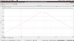
It finally worked absolutely fine, attached is a screenshot of my response. I would like to thank you for taking the time to help in the past few days you were absolutely great. I sincerely appreciate the time you spent reviewing my steps and even recommending different designs for achieving my intended response. Your advice was very helpful and I wouldn't be here if it weren't for you

I especially appreciate your offer deriving my transfer function and even taking part of your time to simulate my circuit. Once again thank you!
 

Attachments

  • FIlter (2).png
    FIlter (2).png
    62 KB · Views: 65

Re: Butterworth transfer function transformation to tow thomas gm c

IMG_20180312_093911.png

Just a quick tip, if for a non ideal circuit I am going to implement this circuit instead of each vccs, what I used to do to design Opamps before was to just keep adjusting the bias current and the dimensions of each transistor until I reach the value intended, however this method takes alot of time as it is only based on trial and error i do not calculate any numbers or design parameters, so my question is there a faster way than mine to just keep trying until I reach my intended value? I know that i must end up with trying and failing however in light of what i understand i do not calculate any numbers or any range to work on I just adjust all dimensions and bias current blindly and i do not know if there are key parameters to adjust to ease the reach to my gm value, so if there is a faster method it would be great because I need to deliver the non ideal circuit in just a week or two and what I do it would take around 2-4 days for each ota depending on how much time i spend on it
 

Re: Butterworth transfer function transformation to tow thomas gm c

OTA-C.PNG

while designing the first OTA, the top left transistor and the bottom left transistor are in triode region and I have no idea how to reach saturation region in both, any ideas ?
 

Re: Butterworth transfer function transformation to tow thomas gm c

You have only mV Vds, unsuitable bias of the cascode transistors, obviously.
 

Re: Butterworth transfer function transformation to tow thomas gm c

well I do not understand? how can I adjust the Vds bias ?

- - - Updated - - -

I am applying a low energy Bluetooth receiver, my maximum vdd is 1.2 unfortunately
 

Re: Butterworth transfer function transformation to tow thomas gm c

You have V2 an V4 to adjust the cascade bias. I'm no sure if the transistor sizes are chosen appropriately.
 

Re: Butterworth transfer function transformation to tow thomas gm c

You have V2 an V4 to adjust the cascade bias. I'm no sure if the transistor sizes are chosen appropriately.


all my transistor lengths in all the circuit are 1u , the widths are varying from one another as when the transistors wasn't biased I started altering the widths, some are 2u some are 4u some are 10, but I couldn't bias the top left and bottom left ones correctly yet, always in triode or even subthreshold region sometimes, which widths should i adjust and should i adjust the my 1u lengths?
 
Last edited:

Re: Butterworth transfer function transformation to tow thomas gm c

I'm not in the IC design business, but my incomplete knowledge tells me that you have basic issues with transistor scaling or designed circuit currents. Just look at the vdsat numbers and realize that the cascode circuit has no available voltage swing.

well the circuit is a mess as when I designed the circuit the first time with logical transistors scaling and voltage sources these 2 exact transistors the top left and bottom left weren't biased correctly so I tried editing some of the lenghts and widths to see their effect but I failed
 

Status
Not open for further replies.

Similar threads

Part and Inventory Search

Welcome to EDABoard.com

Sponsor

Back
Top