Continue to Site

Welcome to EDAboard.com

Welcome to our site! EDAboard.com is an international Electronics Discussion Forum focused on EDA software, circuits, schematics, books, theory, papers, asic, pld, 8051, DSP, Network, RF, Analog Design, PCB, Service Manuals... and a whole lot more! To participate you need to register. Registration is free. Click here to register now.

Chassis ground/return

Status
Not open for further replies.

Smillsey

Member level 5
Joined
Jul 7, 2014
Messages
91
Helped
0
Reputation
0
Reaction score
1
Trophy points
1,288
Activity points
2,121
Hi all

I have a quick question regarding grounding PCB’s to the chassis.

Do you have your own personal rules as to when you “do” and “don’t”?

I am designing a soft “on/off” switch to control an ATX power supply.

I have currently laid the PCB out and the ground returns flow back to the ATX PSU via directly via a cable loom. They do not flow via the chassis ground.

I see no reason to use the chassis as the ground return for these DC signals, as I do not want ground loops nor do I want to use the aluminium chassis as the ground return.

I will be designing the analog measurement boards next and I plan to run those grounds back to the ATX PSU too.

The ATX design guide doesn’t really mention ground return best practices.

My plan is to only use the chassis as a ground path for the shielding cans.

Does anybody here use the chassis as a return path for anything else?

Thanks

S
 

I see no reason to use the chassis as the ground return for these DC signals

In fact, the chassis of the equipment should be "Earth'ed", not "Ground'ed", which means that in order to prevent injury to the user in case of either some internal or external dangerous voltage being short-circuited to the chassis, all this charge would be drawn to the Earth.
 

You want to hold the chassis at safe potential and give
incident EMI somewhere to go. Third prong most likely.

You do not want to make return currents of the power
distribution network travel through the case.

I like a star ground for everything.
 

Sorry, I have not been clear.

I will of course be earthing the chassis as per the relavent safety standards.

I am referring to grounding the PCB 0V, which I have seen on some products... Where low voltage lines use the chassis as a return path to the source (not the high voltage input), ie the 12V rail for example.

To be clear, I do not like the idea of using the chassis as a return path - even for voltages considered “safe”.

- - - Updated - - -

You want to hold the chassis at safe potential and give
incident EMI somewhere to go. Third prong most likely.

You do not want to make return currents of the power
distribution network travel through the case.

I like a star ground for everything.

Hi Dick

I like the star ground too.
 

To hopefully clarify further - I am referring to the concept edaboard user Betwixt discusses in this thread;

https://www.edaboard.com/showthread.php?t=191874

Where the signal, chassis and earth grounds are tied together.

I am not referring to the neutral return to the mains supply.
 

Hi,

This discussion is confusing.
I see no clear concept of wiring your questions refer to. So please post a sketch of your situation.

***
Earth:
Afaik. in an ATX power supply the supply case is earthed. If you mount this power supply in a metal PC case, then automatically the PC case is earthed, too.
So any other metal case (HDD) mounted into the PC case is earthed automatically (There is no need to earth this other case. And I´d avoid an extra earth wire to prevent from loops)
But you are free to use a circuitry to connect this case with your PCB_signal_GND. I recommend an RC combination, to avoid low impedance GND loops, but to avoide high voltage (ESD) between case and PCB. Maybe a high voltage 1nF capacitor in parallel with an 1M Ohms resistor. The capacitor acts somehow as a voltage divider for ESD. And it acts as low impedance path for EMI. The resistor is a DC path to reduce/dissipate ESD voltages.

Signal_GND:
I strongly recommend not to use case as return path.

Klaus
 

I will send a schematic tonight.

I have a good idea now of what to do.
 

Hi all

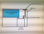
Here is a schematic of my situation...

IMG_5933.jpg

The instrument will use an ATX power supply which has 12V and 5V rails I will be using. The PSU is turned on and off using a P_ON pin.

The 0V returns for all rails at the output of the PSU are all connected to chassis ground the the PSU end (unless you connect these outputs to the chassis somewhere in your system).

My thinking is to use a single point ground reference for all PCB's in the system at the "PSU end". This would prevent ground loops. In essence, while the chassis is connected to 0V (and a continuity check from any 0V line would confirm the chassis is connected to 0V) it does not provide the return paths from the "soft power switch circuit" or any other PCB in my diagram as I will run a 0V return wire (or thick track) back to the PSU.

If I grounded the "soft power switch" PCB using standoffs and mounting holes connected to the PCB ground plane it would mean current would be flowing in the chassis and/or the 0V return. While at these voltages this is safe practice I just don't like this idea. I have the space, budget and engineering time to implement a single point ground at the PSU output - i cannot see any reason not to unless I am missing something?

I do plan to use the mounting holes to connect my analogue measurement pcb shielding cans to the chassis. Effectively creating a Faraday cage around measurement circuits.

What are your thoughts on a chassis grounded shielding can enclosing a circuit which has a ground reference back at the PSU? My theory is the shield would divert any EMI straight to the chassis away from the sensitive circuit... I need to research more into this approach as I am a little concerned this is going to cause issues.

If you look at the "analog measurement circuitry" blue section in the diagram above, my plan is to use the same PSU ground as I definitely do not want to create ground loops through the chassis.

I suppose this could be considered a "star" configuration on a systems level.

Any thoughts? Any glaring "no no's"?

Thanks all!
 

Hi,

the picture isn`t very helpfull. It is of bad quality and - as far as I can see - it doesn´t show the connections and isolations you are talking about.
Picture: It seems to be a photo of a PC screen. Why not simply use a screenshot uploaded as *.PNG?

* don´t connect the "soft power switch" PCB_GND directely to the metal case. Use isolated PCB holes or isolating standoffs. It is not clear form your picture if there is a case (metal? plastic?) around the soft power switch PCB. I expect the PCB includes the switch. If this is a switch in a metal case than you may need to take care about ESD.

* use the star_GND near your PS

I do plan to use the mounting holes to connect my analogue measurement pcb shielding cans to the chassis. Effectively creating a Faraday cage around measurement circuits.
What exactly does this mean regarding analog_GND, shielding faraday cage and metal case? This is what your picture is meant to clarify.
BTW: a faraday cage doesn´t necessarily need a connection to the circuit.
Your metal case already acts like a big faraday cage. So why another faraday cage inside this big faraday cage? I assume there is some information missing.

Klaus
 

Hi,

the picture isn`t very helpfull. It is of bad quality and - as far as I can see - it doesn´t show the connections and isolations you are talking about.
Picture: It seems to be a photo of a PC screen. Why not simply use a screenshot uploaded as *.PNG?

* don´t connect the "soft power switch" PCB_GND directely to the metal case. Use isolated PCB holes or isolating standoffs. It is not clear form your picture if there is a case (metal? plastic?) around the soft power switch PCB. I expect the PCB includes the switch. If this is a switch in a metal case than you may need to take care about ESD.

* use the star_GND near your PS

What exactly does this mean regarding analog_GND, shielding faraday cage and metal case? This is what your picture is meant to clarify.
BTW: a faraday cage doesn´t necessarily need a connection to the circuit.
Your metal case already acts like a big faraday cage. So why another faraday cage inside this big faraday cage? I assume there is some information missing.

Klaus


In hindsight, that schematic is awful :-(

Ref ESD - I don’t think I will have an issue as theswitch has a rubber cap which will have a very high dielectric strength.

The second Faraday is to reduce noise from the ATX switching PSU.

I will try to put together a full schematic which is more helpful.

Your comment stating shields do not necessarily need to connect to the circuit inside them answers my question.

I will design the analogue PCB so that tests can be perform with and without the second faraday cage.

If anybody is interested I will post up results as to how much noise the ATX influences my sensitive circuitry.

The switch/button is on the PCB and the case is aluminium.

Thanks Klaus I appreciate your input.
 

Hi,

The second Faraday is to reduce noise from the ATX switching PSU.
If there is sensitive analog circuit, then I´d rather concerned about "conductive noise"... --> proper filtering of the signals/wires from power supply to the analog circuitry.

Klaus
 

Hi,


If there is sensitive analog circuit, then I´d rather concerned about "conductive noise"... --> proper filtering of the signals/wires from power supply to the analog circuitry.

Klaus

Yes I am going to be investigating various conducted noise suppression techniques.

I will use a combination of ferrite, filtering and linear regulation. I need to be careful with capacitive loading on the PSU.
 

Hi,

An ATX supply is made for a lot of power. Does your analog circuit need that much power?
Don´t run into some kind of "underpower" conditions of the ATX supply with further increased voltage ripple.
The voltages of an ATX supply may carry ripple and are not that precise..
Are you sure this is a good choice?

Klaus

Hi Klaus

You raise a good point, the PSUÂ’s IÂ’m looking at have a ripple voltage of around 2-5mV.

This is huge but I am planning on implementing filtering and linear regulation but I am yet to perform tests of performance.

Total power requirements will be around 100W continuous, do you have any preferences for a universal input, PFC corrected power block?

I will test the circuit using a large battery and then with the PSU to compare noise influence.

I now have decided to use a star ground type system whereby I will run the grounds back to the PSU.

Next issue on my mind is shielding of the sensitive analogue signal conditioning.

I will be installing a shield over the sensitive circuits, like these : https://hollandshielding.com/Fixed-PCB-shielding-cans

I plan to ground the can at a single point to the chassis rather than ground it at multiple points all around the can, is this a good idea? I donÂ’t want to create ground loops and a lot of literature recommends single point grounding of any shield.

Does there need to be a via fence from the top plane (to which the shield can is soldered to) to either a dedicated shield ground plane or the 0V ground plane?

Or are the fingers on the shields going to provide enough of a faraday cage around the sensitive circuit?

Thanks
 

Hi,

I need a picture where I can see connections and isolations.
A piece of paper and two colored pencils ...

Klaus
 

Status
Not open for further replies.

Similar threads

Part and Inventory Search

Welcome to EDABoard.com

Sponsor

Back
Top