Continue to Site

Welcome to EDAboard.com

Welcome to our site! EDAboard.com is an international Electronics Discussion Forum focused on EDA software, circuits, schematics, books, theory, papers, asic, pld, 8051, DSP, Network, RF, Analog Design, PCB, Service Manuals... and a whole lot more! To participate you need to register. Registration is free. Click here to register now.

AD 9833 strange sine behaviour or is it the scope?

Status
Not open for further replies.

Garyl

Full Member level 5
Joined
Mar 28, 2017
Messages
253
Helped
6
Reputation
12
Reaction score
7
Trophy points
18
Activity points
2,633
Hey,
I just want to make sure if that's normal..
The AD is driven by Arduino, it's a square/sine signgal generator rated up to 12.5MHz.
It's powered by 5V.
The used Arduino library is here: https://github.com/Billwilliams1952/AD9833-Library-Arduino
The used clock source is 24MHz.
The SQUARE wave is disorted even at 1 MHz:
IMG_20180224_185357.jpg
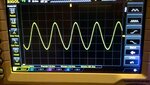
The sine wave is good at 1MHz, but at 8MHz is "dancing", please watch the video (in zip file):
View attachment dancingsine.zip

The signal generator supply has 100nF SMD capacitor near pins, then a 100nF tantalum THT capacitor, and then 470uF electrolytic capacitor.
I can't think of any reason why the waveforms are not perfect, maybe it's just that they should look like this way?
 

It's not really clear what your circuit is, but that doesn't look great. Maybe it's a measurement problem, especially if you've got a long lead for your oscilloscope ground lead. I couldn't open your zip file, so I don't know what you mean by "dancing"; do you mean the D.C. Level is changing?

Can you simulate your input to the ADC ( the output of the arduino)? That might give you a clue. You need to first determine if this is a hardware or software problem.
 

I don't think that I can use Arduino ADC to check anything at 8MHz.

Here is how my connection looks like: basic circuit (Arduino UNO is connected to AD 9833 by SPI):
AD9833-waveform-generator-circuit.png
AD 9833 chip board:
ad9833.png

I've tried to upload the scope movie as gif, but it does not work on the forum, so all I can show is the zip file from first post. It looks like both amplitude and period is changing a little all the time.
 

Attachments

  • dancingsine.jpg
    dancingsine.jpg
    165.9 KB · Views: 224

The ringing you have on the square wave could be do to uncorrect probing, but the sinewave behaviour seems something related to sampling. I have had a look to the arduino library and I read that it uses a 25 MHz clock. probably you have to adjust something in the software to allow the use of a 24 MHz clock.
 
  • Like
Reactions: Garyl

    Garyl

    Points: 2
    Helpful Answer Positive Rating
The ringing you have on the square wave could be do to uncorrect probing, but the sinewave behaviour seems something related to sampling.
Probe is 1X, ground connected to 7805 case...


I have had a look to the arduino library and I read that it uses a 25 MHz clock. probably you have to adjust something in the software to allow the use of a 24 MHz clock.
You are right, but I have already taken it into account. It's very easy to set clock value in this lbirary:

Code C - [expand]
1
2
//AD9833 gen(FNC_PIN);       // Defaults to 25MHz internal reference frequency
AD9833 gen(FNC_PIN, 24000000UL);       // CHANGED - use 24MHz of my clock source


I have done that already and I think it's not related to the noise problem.

PS: I need only frequencies up to 8MHz
 

Hi,

What about a x10 probe?
You need a solid GND plane. And the probe_gnd needs to be very close to the IC_GND. (Not voltage regulator)

But I assume this may improve waveform a little, but there is another issue.

Klaus
 

10x probe and better ground probe connection is not changing much.

The square wave output is more looking like a sine at 5MHz or so...

The chip is on bottom side of twosided board, the top side is entirely GND, there is also ground around it and ground vias connecting top and bottom ground.

The worst thing is I don't know how common is this behaviour, I have ordered a factory-made AD 9833 board but I will have to wait for it a month or so...
 

Hi,

the top side is entirely GND,
Don't compare a copper_pour with a good GND_plane.
Copper pour on top layer is almost useless in my eyes, because the traces and the SMD pads cut the GND in pieces.
You see the big areas of copper, but for a useful analysis you need to focus on the weak, long and thin connections, the return paths of signals, the resulting area that is enclosed by a signal loop.

Klaus
 

Don't compare a copper_pour with a good GND_plane.
Copper pour on top layer is almost useless in my eyes, because the traces and the SMD pads cut the GND in pieces.
You see the big areas of copper, but for a useful analysis you need to focus on the weak, long and thin connections, the return paths of signals, the resulting area that is enclosed by a signal loop.

The return paths of digital SPI control, or the analogue signal output? I can show the PCB if it helps.


I have also searched the web more and found out that AD 9833 for some reasons is not used at higher frequencies. For example here:
https://www.arrl.org/files/file/QEX_Next_Issue/May-Jun_2013/Fernandes_QEX_5_13.pdf
Clean sine waves from 0.1 Hz to 3 MHz, triangular waves up to 300 kHz,
quare wave, pulse generator and sweep.
Frequency — 0.1 Hz to 3 MHz for sine
waves and square waves and 0.1 Hz to
300 kHz for triangular waves. The stability
with temperature not measured is probably
around 5 ppm from 20 to 30°C
why are they also using AD 9833 up to only 3MHz and not to the maximum frequency specified in the datasheet?
 

Attachments

  • Fernandes_QEX_5_13.pdf
    3.6 MB · Views: 115

I don't see your AD9833 output circuit in any of the posts. It's pretty clear that DDS generators need an output low pass filter to produce clear sinewave signals. Don't blame the chip for inappropriate circuit design.

why are they also using AD 9833 up to only 3MHz and not to the maximum frequency specified in the datasheet?

Increasing the ratio of MCLK to maximum output signal frequency relaxes the low-pass (or "reconstruction") filter requirements. Details are discussed in the linked arrl article.
 

Hi,

I assume it has to do with the way the output is beeing generated = DDS and the low pass filter at the output.

For sure a DDS - as is - can´t genrate a pure sinewave.....and on the other side a passive low pass filter can´t work as exact as you need it.
The LPF needs to reproduce high frequency signal with low attenuation but needs to suppress unwanted overtones that they become negligible.

Klaus
 

I looked at the 'dancing sine' video. That's probably normal with the AD9833 at that setting. Your Rigol is showing 8MHz, so you're right at the max limit that the DDS can produce with a 24MHz clock, as you're only getting 3 samples per sine. The anti-aliasing filter is doing it's best to turn that into a true sine, but it's messy with only 3 samples. At the 3MHz rated maximum, you'd have 8 samples per sine, which should have a lot less 'dancing'.

AD has a different (somewhat-related) DDS chip if you truly need to hit >3MHz speeds or higher: AD9851. It only as sine and square outputs, but who really uses triangle waves at those frequencies for anything other than play? I can see uses for variable speed programmable sawtooth ramps, but not for triangles. The AD9851 does an internal multiply-by-6 on your reference clock so you can hit 70MHz output frequencies cleanly. I've seen breakout boards for the AD9851 at the same kinds of places that sell the AD9833 boards. There's a new revision of the board that's better than the older one, so look around before you buy. There are also some with a micro and display, like this one:

s-l1600.jpg

The top of the board looks OK, but if it's only a 2-layer board then they screwed up the ground plane on the back side with that trace that cuts right through the filter section. That'll throw some nasty spurs into the mix if it's only a 2-layer board.
 

Status
Not open for further replies.

Similar threads

Part and Inventory Search

Welcome to EDABoard.com

Sponsor

Back
Top