Continue to Site

Welcome to EDAboard.com

Welcome to our site! EDAboard.com is an international Electronics Discussion Forum focused on EDA software, circuits, schematics, books, theory, papers, asic, pld, 8051, DSP, Network, RF, Analog Design, PCB, Service Manuals... and a whole lot more! To participate you need to register. Registration is free. Click here to register now.

Why is the internal resistance of brush DC motor not constant ?

Status
Not open for further replies.

anotherbrick

Full Member level 4
Joined
Jan 10, 2009
Messages
217
Helped
1
Reputation
2
Reaction score
1
Trophy points
1,298
Location
Istanbul , Turkey
Activity points
3,143
hello dear forum,

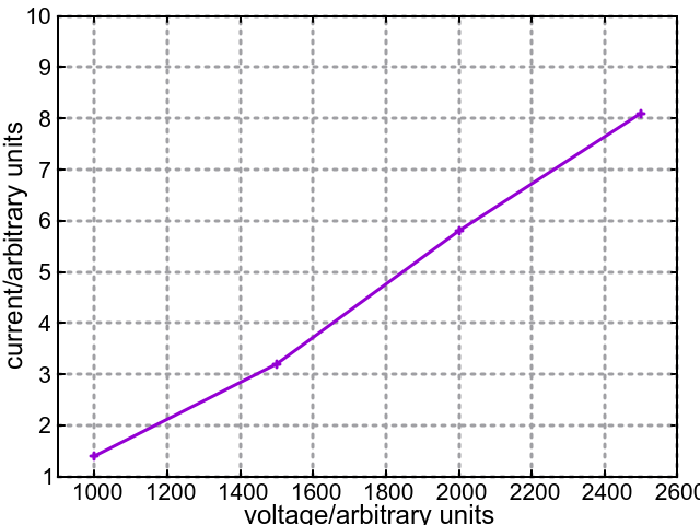
I am applying different PWM values to a 24 V brush DC motor

and taking some measurements of armature current,

becouse I want to calculate armature resistance

however the armature resistance is changing with applied PWM

here is what I measured;

PWM | current | internal resistance
-------------------------------------------------
1000 | 1.4 | 710
1500 | 3.2 | 470
2000 | 5.8 | 350
2500 | 8.1 | 310

I assumed the applied voltage is linearly changing with applied PWM
and locked the motor shaft and calculated a number which must be the
internal resistance multiplied with a constant

I used the equation PWM = I x R (resistance x constant)

my question ;
why is the number representing the internal resistance not a constant ?

my aim was to calculate the motor speed from the equation
V = EMF + I x R
however I got a changing resistance value and I couldnot calculate the speed

please advice

thank you
 

"I used the equation PWM = I x R (resistance x constant)"

How you derived and validated this?


To measure armature resistance, lock the rotor (as you did), and then use a 4-wire ohmeter measure the resistance. As simple as that.

You may also want to operate the motor at full load, so the winding gets at proper operating temperature, and re-measure the resistance.

If the latter is not feasible, you can estimate what the temperature rise will be, and calculate the resistance increase from the cold rotor; based on the 0.0039/C resistance-rise characteristic of copper.
 
Besides unclear scaling of "PWM", to cancel EMF effect in your measurement, you need to stall the motor. Did you?

It can be also expected that your motor driver involves series resistance and voltage drops, so you better measure the average motor voltage empirically instead of calculating it from PWM control value.
 
- I locked the rotor

- I assumed that the voltage applied to the motor is roughly changing linearly with the PWM
i.e. V = PWM x a constant

that way I assumed PWM = (I x R) / k and I calculated from experimental data (R / k)

so (R / k) contains all the normalizing constants resulting from above equation

my question ;

- what is wrong with my ( rough ) assumption ?
- why is the resulting (R / k) not near to a constant ?

I know I can measure internal resistance with AVOmeter but
how can I trust this measurement if the resistance is changing with applied voltage i.e. not a constant ?
the measured resistance must be in accordance with experimental data - isnt ?
 

Hi,

Measuring voltage and current is not as simple as it seems:
You need to know what you are doing ... or what your measurement device is doing.

Average voltage = DC_voltage x duty_cycle
RMS voltage = DC_voltage x sqrt(duty_cycle)

Klaus
 
If you assume a constant voltage drop of pwm output stage (simplified first order estimation), you get always constant resistance from your measurement.
 
If you assume a constant voltage drop of pwm output stage (simplified first order estimation), you get always constant resistance from your measurement.
An offset in the output voltage is the simplest way to explain the strange trend. But that offset would have to be pretty substantial (subtract roughly 700 from PWM). I would also suspect the current measurement has errors in it. How are you measuring winding current?
 
"how can I trust this measurement if the resistance is changing with applied voltage i.e. not a constant ?
the measured resistance must be in accordance with experimental data - isnt ? "


Only if the experiment and the test equipment are properly set up. For instance how, and with what are you measuring the current and voltage.
This is not a sarcastic question. If the current probe is one designed for 50/60 Hz use, it may have significant errors with higher PWM frequencies and /or high crest factors. Same with cheap DMMs

Also, if the PWM frequency -which you have not mentioned- is high, the rotor's inductance should also be taken into consideration.

Do you have a scope? Can you show us the voltage and current waveforms?
 
Just for fun, replace the motor with a 100E resistor and see whether your calculations are working - I guess you will find strange effects.

Then if your meter is a RMS reading one, it may not work well with PWM that can be rather extreme. You need to test that too.

If your motor is not a big one (that will have a rather low armature resistance) you can simply measure that with the multimeter directly. How does that value compare with your readings?

For small motors, the resistance may depends on the exact position you have locked the motor. You have to worry about that too (the diff may be small and I am not very sure anyway)
 
this is the motor and my PCB

my PWM freq is 10 Khz

I measure current with ACS758 and check with clampmeter UT204

https://www.kartalotomasyon.com.tr/...PR-1623.html?gclid=CJOajZf8vNQCFUlsGwodSTEDWw

clampmeter measures about 0.7 A higher

I take 200 samples with STM32 ADC in 1 ms and average
and I average again 10 of this above average result

kart.JPG
motor.JPG
 

200 samples at 1 msec rate is 5 usec per sample.

10 Khz with a 50% duty cycle will be also a 5 usec pulse.....the pulse will become even shorter with a lower duty cycle.

You are violating Nyquist.


that, in addition to the fact that the motor's inductance will alter its waveshape.
 
Just for fun, I plotted your data. See the results:


The I-V curve is a straight line and that means the resistance is constant.

The curve does not pass through the origin and that means your current and voltage readings are not accurate (offset present).

The slope will give you the resistance of the test load.
 
First of all, before you start, you need to calibrate your setup with a resistor of known (accurate) value. You must also see what kind of results you get with a capacitor used in place of a resistor.
 

Status
Not open for further replies.

Similar threads

Part and Inventory Search

Welcome to EDABoard.com

Sponsor

Back
Top