Continue to Site

Welcome to EDAboard.com

Welcome to our site! EDAboard.com is an international Electronics Discussion Forum focused on EDA software, circuits, schematics, books, theory, papers, asic, pld, 8051, DSP, Network, RF, Analog Design, PCB, Service Manuals... and a whole lot more! To participate you need to register. Registration is free. Click here to register now.

[SOLVED] ds3231 I2C1_Wr Issue

Status
Not open for further replies.

djeceymca

Junior Member level 2
Joined
Mar 17, 2017
Messages
22
Helped
0
Reputation
0
Reaction score
0
Trophy points
1
Activity points
196
Hello Guys,

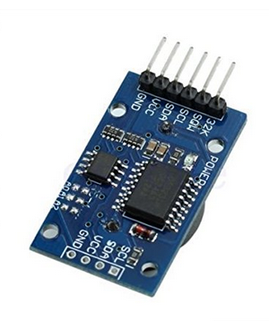
I am trying to connect DS3231 RTC to my PIC microcontroller 18f46k22. But my code is getting stuck at I2C1_Wr(DS3231_Write_addr) command. Any idea whats the issue.


Code C - [expand]
1
2
3
4
5
6
7
8
9
10
11
12
13
14
15
16
17
18
19
20
21
22
23
24
25
26
27
28
29
30
31
32
33
34
35
36
37
38
39
40
41
42
43
44
45
46
47
48
49
50
51
52
53
54
55
56
57
58
59
60
61
62
63
64
65
66
67
68
69
70
71
72
73
74
75
76
77
78
79
80
81
82
83
84
85
86
87
88
89
90
91
92
93
94
95
96
97
98
99
100
101
102
103
104
105
106
107
108
109
110
111
112
113
114
115
116
117
118
119
120
121
122
123
124
125
126
127
128
129
130
131
132
133
134
135
136
137
138
139
140
// LCD module connection
sbit LCD_RS at LATD4_bit;
sbit LCD_EN at LATD5_bit;
sbit LCD_D4 at LATD0_bit;
sbit LCD_D5 at LATD1_bit;
sbit LCD_D6 at LATD2_bit;
sbit LCD_D7 at LATD3_bit;
 
sbit LCD_RS_Direction at TRISD4_bit;
sbit LCD_EN_Direction at TRISD5_bit;
sbit LCD_D4_Direction at TRISD0_bit;
sbit LCD_D5_Direction at TRISD1_bit;
sbit LCD_D6_Direction at TRISD2_bit;
sbit LCD_D7_Direction at TRISD3_bit;
 
#define DS3231_Address              0x68
#define DS3231_Read_addr            ((DS3231_Address << 1) | 0x01)
#define DS3231_Write_addr           ((DS3231_Address << 1) & 0xFE)
typedef signed short int8;
int8 err;
 
unsigned short read_ds3231(unsigned short address){
  unsigned short read_data;
  Lcd_Cmd(_LCD_CLEAR);
  Lcd_Cmd(_LCD_CURSOR_OFF);
  Lcd_Out(1,1, "Before start ");
  Delay_ms(1000);
  I2C1_Start();
  Lcd_Cmd(_LCD_CLEAR);
  Lcd_Cmd(_LCD_CURSOR_OFF);
  Lcd_Out(1,1, "Before 0xD0 ");
  Delay_ms(1000);
  I2C1_Wr(DS3231_Write_addr);
  Lcd_Cmd(_LCD_CLEAR);
  Lcd_Cmd(_LCD_CURSOR_OFF);
  Lcd_Out(1,1, "Before address ");
  Delay_ms(1000);
  I2C1_Wr(address);
  Lcd_Cmd(_LCD_CLEAR);
  Lcd_Cmd(_LCD_CURSOR_OFF);
  Lcd_Out(1,1, "Before RS ");
  Delay_ms(1000);
  I2C1_Repeated_Start();
  Lcd_Cmd(_LCD_CLEAR);
  Lcd_Cmd(_LCD_CURSOR_OFF);
  Lcd_Out(1,1, "Before 0xD1 ");
  Delay_ms(1000);
  I2C1_Wr(DS3231_Read_addr);
  Lcd_Cmd(_LCD_CLEAR);
  Lcd_Cmd(_LCD_CURSOR_OFF);
  Lcd_Out(1,1, "Before Read ");
  Delay_ms(1000);
  read_data = I2C1_Rd(0);
  Lcd_Cmd(_LCD_CLEAR);
  Lcd_Cmd(_LCD_CURSOR_OFF);
  Lcd_Out(1,1, "Before stop ");
  Delay_ms(1000);
  I2C1_Stop();
  Lcd_Cmd(_LCD_CLEAR);
  Lcd_Cmd(_LCD_CURSOR_OFF);
  Lcd_Out(1,1, "Before return ");
  Delay_ms(1000);
  return (read_data);
}
 
unsigned char MSB(unsigned char x){
  return ((x>>4)+'0');
}
 
unsigned char LSB(unsigned char x){
  return ((x & 0x0F) + '0');
}
 
// Global Variable
int second;
int minute;
int hour;
int hr;
int day;
int dday;
int month;
int year;
 
char time[] = "00:00:00";
char date[] = "00-00-00";
 
void main() {
  ANSELD = 0;
  TRISD = 0;
  OSCCON = 0x66;
  Lcd_Init();
  I2C1_Init(10000);
  Lcd_Cmd(_LCD_CLEAR);
  Lcd_Cmd(_LCD_CURSOR_OFF);
  Lcd_Out(1,1, "Time: ");
  Lcd_Out(2,1, "Date: ");
  
  TRISB0_bit =0;
  TRISC0_bit = 1;
  LATB.B0 = 0;
  
  while(1){
           if(PORTC.RC0 == 0){
                        Delay_ms(1);
                        if((PORTC.RC0 == 0)&(LATB.B0 == 0)){
                                LATB.B0 = 1;
                                second = read_ds3231(0);
                                minute = read_ds3231(1);
                                hour = read_ds3231(2);
                                hr = hour & 0b00011111;
                                dday = read_ds3231(3);
                                day = read_ds3231(4);
                                month = read_ds3231(5);
                                year = read_ds3231(6);
 
                                time[0] = MSB(hr);
                                time[1] = LSB(hr);
                                time[3] = MSB(minute);
                                time[4] = LSB(minute);
                                time[6] = MSB(second);
                                time[7] = LSB(second);
 
                                date[0] = MSB(day);
                                date[1] = LSB(day);
                                date[3] = MSB(month);
                                date[4] = LSB(month);
                                date[6] = MSB(year);
                                date[7] = LSB(year);
 
                                Lcd_Out(1,7, time);
                                Lcd_Out(2,7, date);
 
                                Delay_ms(100);
                        }
                }
                else {
                        LATB.B0 = 0;
                }
  }
}


Regards,
Dev
 
Last edited by a moderator:

Hi,

What happens?
Error description?
Scope picture?

Klaus
 

Hello KlausST,

I am getting "Before 0xD0" message in my LCD display.
 

Show circuit. It might be missing 4.7k Pullup resistors on the I2C Bus.

This

Code:
I2C1_Init(10000);

should be

Code:
I2C1_Init(100000);
 

Hello Guys,

I did try with changing I2C1_Init(100000); but no luck. Also tried with Pull up resistance but still the same issue.

Below is the circuit diagram. Its working in proteus but not on real hardware.


Also I am using DS3231 module below is screen shot.


Regards,
Dev
 

Try use I2C SW driver. A made this one and it works perfect.
**broken link removed**
 

Hello Easyrider83,

I really appreciate you suggesting me to work through your soft driver.
But with all due respect I hope mikroC I2C library works fine as its working for others. Apart i did try with mikroC soft I2C library as well.

Do you any suggestion why my code is getting stuck at I2C1_Wr command and any way to fix it?

Regards,
Dev
 

I can provide further help if you zip and post the complete mikroC project files and Proteus file.

Edit:

Try configuring I2C pins as input pins by using TRISx register.
 

Just noticed that you are using I2C1_xxx functions but connecting I2C2 in the schematic. Please clarify.
 

You are using I2C2 in Proteus Circuit but using I2C1 in code. I don't know how it working in Proteus for you.
 

Hello Okada/Fvm,

Actually I was trying with I2C2 module as well, but the same results.

Okada I also tried with setting TRISC as input, still its getting stuck at I2C wr command.

Code:
// LCD module connection
sbit LCD_RS at LATB4_bit;
sbit LCD_EN at LATB5_bit;
sbit LCD_D4 at LATB0_bit;
sbit LCD_D5 at LATB1_bit;
sbit LCD_D6 at LATB2_bit;
sbit LCD_D7 at LATB3_bit;

sbit LCD_RS_Direction at TRISB4_bit;
sbit LCD_EN_Direction at TRISB5_bit;
sbit LCD_D4_Direction at TRISB0_bit;
sbit LCD_D5_Direction at TRISB1_bit;
sbit LCD_D6_Direction at TRISB2_bit;
sbit LCD_D7_Direction at TRISB3_bit;

typedef signed short int8;
int8 err;

unsigned short read_ds3231(unsigned short address){
  unsigned short read_data;
  Lcd_Cmd(_LCD_CLEAR);
  Lcd_Cmd(_LCD_CURSOR_OFF);
  Lcd_Out(1,1, "Before start ");
  Delay_ms(1000);
  while(!I2C2_Is_Idle()) {
   Lcd_Cmd(_LCD_CLEAR);
  Lcd_Cmd(_LCD_CURSOR_OFF);
  Lcd_Out(1,1, "I2C busy");
  Delay_ms(1000);
  }
  I2C2_Start();
  Lcd_Cmd(_LCD_CLEAR);
  Lcd_Cmd(_LCD_CURSOR_OFF);
  Lcd_Out(1,1, "Before 0xD0 ");
  Delay_ms(1000);
  while(!I2C2_Is_Idle()) {
   Lcd_Cmd(_LCD_CLEAR);
  Lcd_Cmd(_LCD_CURSOR_OFF);
  Lcd_Out(1,1, "I2C busy");
  Delay_ms(1000);
  }
  I2C2_Wr(0xD0);
  Lcd_Cmd(_LCD_CLEAR);
  Lcd_Cmd(_LCD_CURSOR_OFF);
  Lcd_Out(1,1, "Before address ");
  Delay_ms(1000);
  I2C2_Wr(address);
  Lcd_Cmd(_LCD_CLEAR);
  Lcd_Cmd(_LCD_CURSOR_OFF);
  Lcd_Out(1,1, "Before RS ");
  Delay_ms(1000);
  I2C2_Repeated_Start();
  Lcd_Cmd(_LCD_CLEAR);
  Lcd_Cmd(_LCD_CURSOR_OFF);
  Lcd_Out(1,1, "Before 0xD1 ");
  Delay_ms(1000);
  I2C2_Wr(0xD1);
  Lcd_Cmd(_LCD_CLEAR);
  Lcd_Cmd(_LCD_CURSOR_OFF);
  Lcd_Out(1,1, "Before Read ");
  Delay_ms(1000);
  read_data = I2C2_Rd(0);
  Lcd_Cmd(_LCD_CLEAR);
  Lcd_Cmd(_LCD_CURSOR_OFF);
  Lcd_Out(1,1, "Before stop ");
  Delay_ms(1000);
  I2C2_Stop();
  Lcd_Cmd(_LCD_CLEAR);
  Lcd_Cmd(_LCD_CURSOR_OFF);
  Lcd_Out(1,1, "Before return ");
  Delay_ms(1000);
  return (read_data);
}

unsigned char MSB(unsigned char x){
  return ((x>>4)+'0');
}

unsigned char LSB(unsigned char x){
  return ((x & 0x0F) + '0');
}

// Global Variable
int second;
int minute;
int hour;
int hr;
int day;
int dday;
int month;
int year;

char time[] = "00:00:00";
char date[] = "00-00-00";

void main() {
  ANSELB = 0;
  TRISB = 0;
  TRISC = 0xFF;
  OSCCON = 0x66;
  Lcd_Init();
  I2C2_Init(100000);
  Lcd_Cmd(_LCD_CLEAR);
  Lcd_Cmd(_LCD_CURSOR_OFF);
  Lcd_Out(1,1, "Time: ");
  Lcd_Out(2,1, "Date: ");

  while(1){
    second = read_ds3231(0);
    minute = read_ds3231(1);
    hour = read_ds3231(2);
    hr = hour & 0b00011111;
    dday = read_ds3231(3);
    day = read_ds3231(4);
    month = read_ds3231(5);
    year = read_ds3231(6);

    time[0] = MSB(hr);
    time[1] = LSB(hr);
    time[3] = MSB(minute);
    time[4] = LSB(minute);
    time[6] = MSB(second);
    time[7] = LSB(second);

    date[0] = MSB(day);
    date[1] = LSB(day);
    date[3] = MSB(month);
    date[4] = LSB(month);
    date[6] = MSB(year);
    date[7] = LSB(year);

    Lcd_Out(1,7, time);
    Lcd_Out(2,7, date);

    Delay_ms(10000);
  }
}

- - - Updated - - -


Attached MikroC code and proteus file.

I can provide further help if you zip and post the complete mikroC project files and Proteus file.

Edit:

Try configuring I2C pins as input pins by using TRISx register.
 

Attachments

  • RealTimeClock_Proteus.rar
    35.1 KB · Views: 78
  • RealTimeClock_Mikro.rar
    46.8 KB · Views: 73

After making some changes it started working for me. In mikroC PRO PIC project settings PIC18F46K22 was selected but in Proteus file PIC18F26K20 was used. I don't know whether your OSCCON setting was correct or not because I didn't check the datasheet. Proteus was saying noise on I2C lines and hence I changed Oscillator to HS but retained your 8MHz Clock frequency. Code was using I2C2 library but PIC18F26K20 doesn't have I2C2 module and hence in code I changed to I2C1.
 

Attachments

  • RealTimeClock_Mikro - Working.rar
    55.3 KB · Views: 71

Hi Okada,

In proteus I selected 46k22 only and simulated with the code I share with you and its working fine in proteus.
Issue comes when I use real hardware.

After making some changes it started working for me. In mikroC PRO PIC project settings PIC18F46K22 was selected but in Proteus file PIC18F26K20 was used. I don't know whether your OSCCON setting was correct or not because I didn't check the datasheet. Proteus was saying noise on I2C lines and hence I changed Oscillator to HS but retained your 8MHz Clock frequency. Code was using I2C2 library but PIC18F26K20 doesn't have I2C2 module and hence in code I changed to I2C1.
 

In proteus I selected 46k22 only and simulated with the code I share with you and its working fine in proteus.

In the Proteus file you sent me it had PIC18F26K20 as the chip and code has I2C2 library usage and you had compiled the code for PIC18F46K22. Without compiling your project, I tried your .hex file in Proteus and it did not work and hence I changed the PIC to PIC18F26K20 in mikroC.
 

You are right, i might have missed to save proteus project.attaching the proteus project again. Having said that code is working fine but doesn't work in real hardware.

View attachment RealTimeClock_ProteusAgain.rar

In the Proteus file you sent me it had PIC18F26K20 as the chip and code has I2C2 library usage and you had compiled the code for PIC18F46K22. Without compiling your project, I tried your .hex file in Proteus and it did not work and hence I changed the PIC to PIC18F26K20 in mikroC.
 

but doesn't work in real hardware.

Then you have to draw your exact hardware circuit in Proteus and post it here. Are you sure the DS3231 module you are using in hardware is working ? Did you try with another module ?
 

This is the first module I am trying, Is there any way to test hardware if its working or not?
Are you sure the DS3231 module you are using in hardware is working ? Did you try with another module ?
 

I am trying to connect DS3231 RTC to my PIC microcontroller

The circuit diagram you posted has another RTC, the DS1307, but your code makes use of ds3231() functions.
 

Status
Not open for further replies.

Similar threads

Part and Inventory Search

Welcome to EDABoard.com

Sponsor

Back
Top