Continue to Site

Welcome to EDAboard.com

Welcome to our site! EDAboard.com is an international Electronics Discussion Forum focused on EDA software, circuits, schematics, books, theory, papers, asic, pld, 8051, DSP, Network, RF, Analog Design, PCB, Service Manuals... and a whole lot more! To participate you need to register. Registration is free. Click here to register now.

Calculate a Transistor frequency Response with datasheet

Status
Not open for further replies.

baby_1

Advanced Member level 1
Joined
Dec 3, 2010
Messages
415
Helped
1
Reputation
2
Reaction score
1
Trophy points
1,298
Activity points
4,277
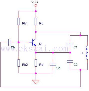
Hello i want to design a collpits oscillator circuit with transistor at 100Mhz frequency.i design and config a circuit but it doesn't work more than 3mhz(when i change capacitor in collpits baias).i think it is related to the transistor frequency response.
could you tell me
1-how can chose a transistor for a desire frequency(Ft , ....)?(for small signal)
2-how can calculate the transistor frequency response with the datasheet? without doing experimental work and using a simulation software
3-what is the best book in S , Y parameters design and theory?(i read Rf Circuit design by bowick)

Thanks
 
Last edited:

Thanks so much SunnySkyguy
could you tell me more about the calculation of a self collpits oscillator with transistor?i know the Avmid but i want to calculate Cb and Ce according this scheme.

57_1335517593.jpg
 

Excuse me SunnySkyguy
but i search in the internet and my books i found that Gain–bandwidth product that show the relationship between gain and bandwidth.could you tell me your reference that say
gain * BW product = fT

Current Gain or Voltage gain?

---------- Post added at 16:31 ---------- Previous post was at 16:05 ----------

i found this
fT, CURRENT–GAIN BANDWIDTH PRODUCT (
MHz)

if means if i use a emitter common bias for a collpits oscillator at 100MHZ i should use a transistor(for example hfe=250) with ft=100MHZ*250=25 Ghz?
 

Please help me....
 

Cb abd Ce are simple HP filters that AC couple the RF signal with low inductance.

Of course BJT's use current gain, FETS use Voltage gain., Op Amps use Voltage Gain.
 
Last edited:

Thanks SunnySkyguy
according your explanation if i use emitter-common that Current gain=100 and for oscillate my circuit in 100Mhz i shoud use transistor with ft 10Ghz?!!!
 

Thanks
could you tell me what is "ss gain"?

in some common emitter how can we control current gain?because its near Hfe constant?
and i see that most fm mixer use a transistor with ft=300 but with voltage gain 10 works fine?how?
 

Dear baby_1
Hi
As you probably know , the frequency response of CE amplifier isn't good . so , at high frequencies , it will create some problems . if you want design high frequency oscillator try CB amplifier , which is good for this aim . a usual mode for this oscillator is a feed back loop from emitter to collector via a capacitor . and a tank circuit in collector .
By the way : there are many rules for oscillator design approaching ! it is possible to design HF oscillators with simpler formulas and approximations .
Best Wishes
Goldsmith
 
  • Like
Reactions: baby_1

    baby_1

    Points: 2
    Helpful Answer Positive Rating
Thanks Goldsmith
yes,CB and CC has more frequency response.but now i want to know the calculation of them but one by one.now im working on CE and theory.could help me on this that what is exactly do for designing a simple colpitts oscillator with transistor in CE mode?

i want to create a colpitts with 100Mhz frequency with 2n3904 or C945 transistor and LC tank.

Any help appreciated
 

Last edited:
  • Like
Reactions: baby_1

    baby_1

    Points: 2
    Helpful Answer Positive Rating
Thanks SunnySkyguy for your response.
i checked most of FM transmitter circuit.you are right both of them they use CB.
could you tell me the designing of collpits oscillator 100MHZ with 2n3904?
 

You can make a sine wave osc @100Mhz if you have a Q of 10 and overall loop gain > 1 with hFE of 3 at 100Mhz from fT of 200MHz, but due to device variable capacitance unless you are using high Q Xtal, it will be unstable. so I advise against that for tolerance issues.

Maybe you want to make illegal FM transmitter on 100MHz with simple VCO and varicap diode??? for learning experience...
 
  • Like
Reactions: baby_1

    baby_1

    Points: 2
    Helpful Answer Positive Rating
Yes according your explanation im working for learning experience
could you suggest books in this filed? i want to read more to know more
any help appreciated
 

Well , lets talk about design rules :
But before that : the point between c1 and c2 ( common point , should be connected to the ground , directly ).
And about value of C1 and C2 , as you probably , know , one of the oscillation laws , is , Av*beta , should be about 1 ( you'd better to set it greater than one ) . and beta is the ratio of C2/C1 and AV is C1/C2 . let me , give you an example : you have Av without feedback that is around 5nf ( for example ) . so C2/C1 should be about 1/5 nf . ( in practice , a bit greater than this .) .and Fr=1/2pi*sqrt(LC) C=C1+C2 .
And about CE amplifier design , i think you know how to design a simple CE amplifier . isn't it?
Best Wishes
Goldsmith
 

Hello and tanks mr.SunnySkyguy
its useful that i use Pspice or ADS for books simulations?
 

Both are important but ADS ($) (Advanced Design Studio , IIRC) is a powerful design tool made by Agilent (former HP) for very complex designs such as RF, telecom, power systems, etc... Being very advanced also means very expensive. $$

It is good you get experience in both and compare to lab tests. Assumptions should be proven.
 
  • Like
Reactions: baby_1

    baby_1

    Points: 2
    Helpful Answer Positive Rating
Status
Not open for further replies.

Part and Inventory Search

Welcome to EDABoard.com

Sponsor

Back
Top