Continue to Site

Welcome to EDAboard.com

Welcome to our site! EDAboard.com is an international Electronics Discussion Forum focused on EDA software, circuits, schematics, books, theory, papers, asic, pld, 8051, DSP, Network, RF, Analog Design, PCB, Service Manuals... and a whole lot more! To participate you need to register. Registration is free. Click here to register now.

Potentiometer Problem with PIC16F877A

Status
Not open for further replies.

xpress_embedo

Advanced Member level 4
Joined
Jul 5, 2011
Messages
1,154
Helped
161
Reputation
396
Reaction score
189
Trophy points
1,353
Location
India
Activity points
10,591
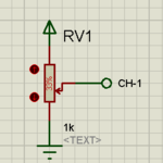
I am using a 1K Pot connected on channel 0 of PIC16F877A to control the phase of the sine wave..

In Proteus its works fine.

I am using 1k POT but it is not showing exactly 1K value...
means value is varying randomly..
it is a 1K POT and sometime showing value around 2k or more than 2K but less than 3k

In my Hardware which i had made..
It gives me problem when i rotate the knob of POT... at some instant my controller stops working..

It gets halted.. I have used an LED which continuously blink when my hardware run..
And this LED glows always when i rotate the knob of My POT quickly..

Some times my Controller gets restarted...
I don't know whether my POT is causing my controller to restart..

I had disable Watch Dog Timer, Power On Reset and Brown Out Reset...

Any Advice..
Surely i am going to change my POT..
But will this fix the Problem..
I have to submit my hardware tomorrow..
So needs help..

Thanks in Advance
 

You are telling us nothing... a pot does not change it's value by itself. How is it connected and how does it control the phase of your sine wave? A schematic would be useful.

Brian
 
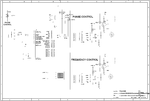
Sorry For Not Posting the Proper Information..

Actually my Circuit is running Properly in Proteus..


sine_wave.png

This is my CODE
Code:
/************************************************************************
THIS FIRMWARE CONTROLS THE FREQUENCY OF SINE WAVE GENERATED AT PORTD OF
PIC16F77A.
AND ALSO GENERATES A SINE WAVE AT PORTC OF PIC16F877A WHOSE PHASE IS ALSO
CONTROLLED BY SOME MEASURES.
AUTHOR ---> ARUN SHARMA, NITIN SINGH RAWAT
DATE   ---> 5th FEBRUARY, 2012
************************************************************************/

#include<htc.h>
#include<math.h>

//Configuration Bit Setting
//__CONFIG(FOSC_HS & WDTE_OFF & PWRTE_ON & BOREN_ON & LVP_OFF);

#define _XTAL_FREQ 20000000
#define LED PORTBbits.RB5
#define UP PORTBbits.RB1
#define DOWN PORTBbits.RB2

/***************************ISR FUNCTION*****************************/
void T1_ISR(void);	//ISR for Generating Delay
void RB0_ISR(void);
/********************************************************************/

/********************INTERRUPT SERVICE ROUTINE***********************/
void interrupt Check_Interrupt(void)
{
	if(PIR1bits.TMR1IF == 1)
		T1_ISR();
	if(INTCONbits.INTF == 1)
		RB0_ISR();
}
/********************************************************************/

//One Degree Resoultion Sine Wave Array
/*********************************************************************************************************************************/
const unsigned char wave[360] = {0,0,0,0,0,0,1,1,1,2,2,2,3,3,4,4,5,6,6,7,8,9,10,11,11,12,13,14,16,17,18,19,20,21,23,24,25,27,28,
    29,31,32,34,35,37,39,40,42,44,45,47,49,50,52,54,56,58,60,62,64,65,67,69,71,73,75,77,80,82,84,86,
    88,90,92,94,97,99,101,103,105,107,110,112,114,116,119,121,123,125,128,130,132,134,136,139,141,143,
    145,148,150,152,154,156,158,161,163,165,167,169,171,173,175,178,180,182,184,186,188,190,192,193,
    195,197,199,201,203,205,206,208,210,211,213,215,216,218,220,221,223,224,226,227,228,230,231,232,
    234,235,236,237,238,239,240,241,242,243,243,244,245,246,247,248,248,249,250,250,251,251,252,252,
    253,253,253,254,254,254,254,254,254,254,255,255,255,254,254,254,254,254,254,254,253,253,252,252,
    251,251,250,250,249,248,248,247,246,245,244,243,242,242,241,240,239,238,237,236,235,234,232,231,230,
    228,227,226,224,223,221,220,218,216,215,213,211,210,208,206,205,203,201,199,197,195,193,192,190,188,
    186,184,182,180,178,175,173,171,169,167,165,163,161,158,156,154,152,150,148,145,143,141,139,136,134,132,
    130,128,125,123,121,119,116,114,112,110,107,105,103,101,99,97,94,92,90,88,86,84,82,80,77,75,73,71,69,67,
    65,64,62,60,58,56,54,52,50,49,47,45,44,42,40,39,37,35,34,32,31,29,28,27,25,24,23,21,20,19,18,17,16,14,13,
    12,11,11,10,9,8,7,6,6,5,4,4,3,3,2,2,2,1,1,1,1,0,0,0,0,0};
/*********************************************************************************************************************************/

/**********************VARIABLE DECLARATION**********************/
unsigned int i=0,j=0;
unsigned char portb_mismatch;
float delay;
unsigned int adc_data = 0x00;
unsigned int timer_value;
signed int frequency_control = 0;
signed int offset = 0;
signed int offset_temp=0;
/****************************************************************/

void main()
{
	TRISD = 0x00;
	TRISC = 0x00;
	PORTC = 0x00;
	TRISD = 0x00;
	TRISB = 0B00000111;
	LED = 1;
	__delay_ms(1000);
	LED = 0;
	__delay_ms(1000);
	LED = 1;		
	__delay_ms(1000);
	TRISAbits.TRISA0 = 1;	//Channel A0 as Input Pin

	T1CON = 0x01;	//Select the Timer-1
	TMR1H = 0xFE;
	TMR1L = 0xCB;
	//Running ADC For the First Time Before Starting the Interrupt
	//So That we Can Acquire the Delay Value
	ADCON0 = 0x81;
	//Fosc/64 is Selected
	//Channel-0 is Selected
	//Analog-to-Digital Converter Module is Powered Up

/*************************************************/
	ADCON1 = 0xCE;	//Only Channel One is Analog Channel while all others are Digital I/O
	//A/D Result Format Select Bit Right Justified
	//and AN0 Channel as Analog Channel
/***************************************************/

/****************ENABLING INTERRUPTS****************/
	PIE1bits.TMR1IE = 1;
	INTCONbits.INTE = 1;	//Enable the External Interrupt
	INTCONbits.PEIE = 1;
	PIE1bits.ADIE = 0;	//Disables A/D Conversion Bit
	INTCONbits.GIE = 1;

	while(1)
	{
		__delay_ms(25);
		LED = ~LED;		
		ADCON0bits.GO = 1;		//Start The Conversion
		//NOTE:-Using a Crystal of 24MHz will create a Problem
		while(ADCON0bits.GO == 1);	//Wait Here for End of Conversion

		/*****************Conversion Finishes Now*****************/

		adc_data = ADRESH & 0x00FF;
		adc_data = adc_data<<8;
		adc_data = adc_data | ADRESL;
		//PHASE CONTROL LOGIC
		offset = round(180*(adc_data/1024.0)) - 90;
		if(offset_temp != offset)*/
		{
			//offset_temp = offset;
			if(offset < 0)
			{
				j = offset + i;
			}
			else if(offset > 0)
			{
				j = i + offset;
			}
			else if( offset == 0 )
			{
				j = i;
			}
		}
		

		timer_value = 65536 - 290 + frequency_control;
		if(i >= 359)
		{
			i=0;
		}
		if(j >= 359)
		{	
			j = 0;
		}
	}
}

//Function Definition's are available Here

void T1_ISR(void)
{
	TMR1H = timer_value>>8;
	TMR1L = timer_value;
	PORTD = wave[i];
	PORTC = wave[j];
	i++;
	j++;
	if(i >= 359)
	{
		i=0;
	}
	if(j >= 359)
	{	
		j = 0;
	}
	PIR1bits.TMR1IF = 0;	//Clear the Timer-1 Flag Bit	
}

void RB0_ISR()
{
	if(UP == 0)			//Means UP Key is Pressed
	{
		frequency_control += 2;
		if(frequency_control >= 100)
		{
			frequency_control = 100;
		}
	}
	else if(DOWN == 0)			//Means Down Key is Pressed
	{
		frequency_control -= 2;
		if(frequency_control < 0)
		{ 
			frequency_control = 0;
		}
	}
	portb_mismatch = PORTB;
	PORTB = 0xFF;
	INTCONbits.INTF = 0;
}


This is How i have connected my 1k POT in Physical Circuit

Capture.PNG

But at some instants it is giving value of 2k or More... It means that my POT faulty..

But can this make my Controller to halt and Restart..
 

I do not have HTC or Proteus but the code doesn't look to have any problem that would cause a crash. I do see that you might have some unwanted distortion in your waveforms because of the delay between loading the high and low bytes of the timer and also because your array is bigger than one page of memory so some extra code may be being inserted by the compiler.

I would suggest using a look up table of 90 degrees then using the symetry of the waveform in the other quadrants to adjust the timer intervals.

Brian.
 
I would suggest using a look up table of 90 degrees then using the symetry of the waveform in the other quadrants to adjust the timer intervals.

First of all thanks...
For your help..
actually i want to do that..
But that comes under optimizing the code...

So firstly i want to run this in my hardware...
But it fails to do so...

Can suggest what may be the possible cause of this...

I haven't used a capacitor between my power supply and gnd
and between pot output terminal and ground..

Actually my hardware works fine..
But when i rotate the knob of POT.. at some instants my Controller gets restarted or Stop..
Is it possible for the controller to Stop..

Pls suggest me some thing..
 

You MUST use capacitors between supply and ground and also make sure you connect both VDD and VSS pins.

The line in your code: "adc_data = ADRESH & 0x00FF;" doesn't do anything so you could remove it. ADRESH is an 8-bit register and the top 6 bits will always be zero anyway.
Change the line following it to: "adc_data = ADRESH << 8;"

I am not sure the math in the calculation is correct, I cannot check here but the ADC result divided by 1024 will always be less then 1 so you might need to use a cast to ensure the result is treated as a floating point number.

Brian.
 
The line in your code: "adc_data = ADRESH & 0x00FF;" doesn't do anything so you could remove it. ADRESH is an 8-bit register and the top 6 bits will always be zero anyway.
Change the line following it to: "adc_data = ADRESH << 8;"

Thank u so much i will remove this..

I am not sure the math in the calculation is correct, I cannot check here but the ADC result divided by 1024 will always be less then 1 so you might need to use a cast to ensure the result is treated as a floating point number.

I don't know exactly how to do this....
Typecasting is the thing u are referring...
 

Not typecasting, that's just giving a meaningful name to an existing number type or structure.

The cast I'm referring to is a type inside '(' and ')' that makes the compiler treat one kind of variable as another. For example you might use:

offset = round(180*((float)(adc_data/1024.0)) - 90;

So the division is treated as though the result is a floating point number. Without it you might find that (adc_data/1024) is always less than 1 so it always evaluates to zero. If it did, instead of reading the pot it would always return "round(180 * 0) - 90" which always gives the same result of -90. Be careful though, this is one of the areas where compilers differ from each other and my example may not be the solution to your problem. It's a clue as to where the problem may lie though. The cast will normally be one of (char), (int), (double) or (float) or one of the unsigned versions of them.

Brian.
 
Okay I will use that..
But my compiler is evaluating it properly no problem in this...
 

I had placed Capacitor between Power Supply and Ground

Potentiometer Knob Terminal and Ground..
Still My Controller gets re-started..

What can i do now..
 

There is nothing inherently wrong with the code.

Can you check some things please:

1. use a voltmeter and confirm the voltage from the pot really is going from zero to 5V.
2. check the supply voltage stays at 5V as you adjust the pot.
3. see if the reset always happens when the pot is producing the same voltage or if it's the rate of change that causes it.
4. break the calculation into two parts, use another variable to hold the result of the ADC calculation before applying the rest of the math. Let us know the result as you turn the pot.

What I'm trying to establish in 1 and 2 is if there is an electrical reason why it happens. In 4 I would like to see exactly what the calculation produces, if it does give a result outsideof the range 0 - 359 (or maybe 255) it might be trying to access non-existent memory or the correct address in the wrong memory page.

Brian.
 
There is nothing inherently wrong with the code.

Can you check some things please:

1. use a voltmeter and confirm the voltage from the pot really is going from zero to 5V.
2. check the supply voltage stays at 5V as you adjust the pot.
3. see if the reset always happens when the pot is producing the same voltage or if it's the rate of change that causes it.
4. break the calculation into two parts, use another variable to hold the result of the ADC calculation before applying the rest of the math. Let us know the result as you turn the pot.

What I'm trying to establish in 1 and 2 is if there is an electrical reason why it happens. In 4 I would like to see exactly what the calculation produces, if it does give a result outsideof the range 0 - 359 (or maybe 255) it might be trying to access non-existent memory or the correct address in the wrong memory page.

Thanks Brian..
I PIC has 10-Bit ADC..

Voltage on Pin Changes properly from 0 to 5V.. Properly...

I thing i noticed...
When i remove +12V Supply and -12V Supply from the Circuit...
Means i am disabling my DAC0808 and OP-AMP of both waves..

And then Rotate my POT-KNOB, no re-start occurs...
It means there is something wrong with my Connection..
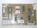
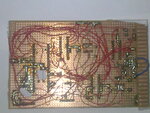
I am attaching my snaps of Hardware...

Photo0186.jpg

Photo0187.jpg

See my Connection this will create problem...
 

I think you have identified the problem. If you are using +12V and -12V supplies on the DAC it is probably dumping current into the PIC pins. If you look at the DAC0808 data sheet, the digital inputs are referenced to the VCC line, in fact the schematic shows them connected directly to the base of transistors while the emitters are tied to VCC. If I interpret that correctly, when using 5V (PIC) drive levels you must use a VCC of 5V on the DAC. It's quite possible you have a situation where the DAC is sourcing current from the +12V supply and dumping it via the PIC to ground.

Brian.
 
I fully don't understand it clearly but obviously got some thing...

I am having +5V-GND +12V-GND-(-12V) Supply in one Power Supply Unit..

If this is happening my controller must get re-started due to insufficient supply..

So what is the Solution for this...

And Why?? all this happens when i rotate the Knob of POT..

Thanks Brian..
What should i do now..
To make my Circuit working Properly
 

I don't think it is because of insufficient supply, I think the problem is that the PIC produces logic levels at it's pins which are from 0V to 5V but if I read the datasheet correctly the DAC inputs are from 0V to whatever the +Ve supply to the DAC is. So you have two choices, either increase the level from the PIC to 12V using a buffer circuit or, reduce the DAC + supply to 5V. My best guess is that the 12V from the DAC appears at it's input pins and overloads the PIC, causing the reset.

Can you temporarily remove the +12V to the DAC and feed it from +5V instead? If it stops the reset it will prove if I am right or not.

Brian.
 

When i remove +12V and -12V supply My Controller doesn't get re-set...
After Placing the Supply i am getting this problem..
I am having a +5V supply in-built in my Power Supply Unit...

Can you temporarily remove the +12V to the DAC and feed it from +5V instead? If it stops the reset it will prove if I am right or not.

I don't understand this..
DAC just use +5V supply and -12V supply not +12V

Op-AMP uses +12V and -12V

After removing Both +12V and -12V.. controller doesn't get reset..
 

Sorry, my misunderstanding. I can't see from your schematic where the DAC supply comes from and you did say that removing +12/-12 disables the DAC.

Can you check some things for me:

1. Remove the PIC from it's socket and reconnect all the supplies. Now measure from each pin to ground and check none of the voltages are higher than 5V.
2. Confirm the values of the two capacitors at the crystal are really 22pF and their ground side is connected as close to the PIC ground as possible.
3. That you have both VSS and both VDD pins connected at the PIC.

It looks like it's either a voltage problem or the inductance of the wiring is causing excessive noise on the clock or reset lines.

Brian.
 

My Crystal Capacitors are 33pF
Voltage Between Vdd and Vss is around 5.04V

What i personally feel is that there is something due to wiring...
It means that i have to redesign the board...
 

Status
Not open for further replies.

Similar threads

Part and Inventory Search

Welcome to EDABoard.com

Sponsor

Back
Top